EasyManua.ls Logo

Austro Engine E4P - 6.6 Electrical System Overview

Austro Engine E4P
56 pages
Print Icon
To Next Page IconTo Next Page
To Previous Page IconTo Previous Page
Loading...
Operation Manual
E4P
E4.01.02
Issue date: 15.Nov.2016
Page: 6-6
Revision no: 1
6.6 Electrical System
The Electrical System consists of the following major Components:
Starter
Generator
GPC Glow Plug Control Unit
EECU Electronic Engine Control Unit
Sensors & Actuators
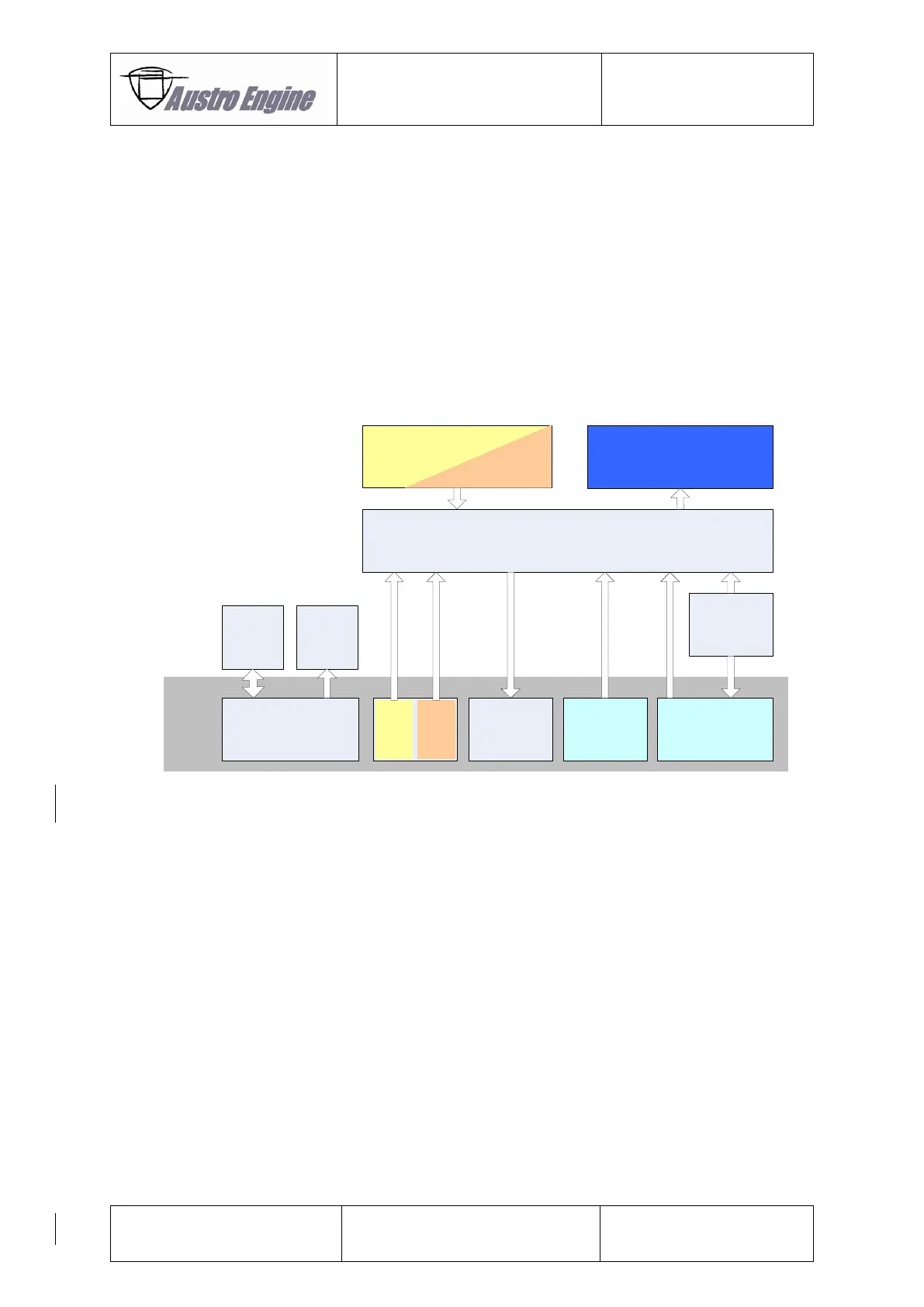
The EECS Block Diagram shows the connection between the EECS components which are used in the
E4P Engine and displays also the Interface from the Airframe to the EECS
of the E4P.
Fig. 6.4: EECS Block Diagram
EECU
Actuators
Glow
Plug
Control
Starter
Generator
A/C
EECS
Engine
Monitoring
System
3way Cockpit
Switch
A/C PowerA/C Interface
Engine Sensors
Power
Lever

Related product manuals