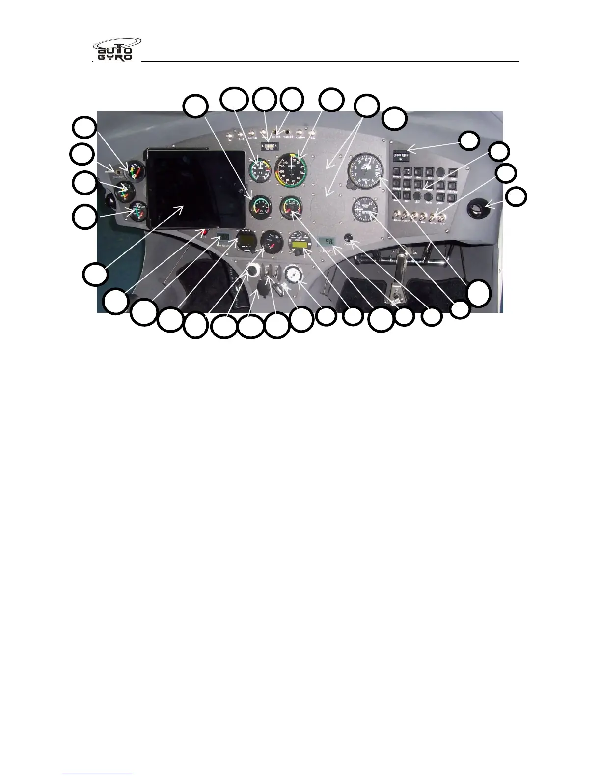
1 – Hour meter 17 – Fuel level indicator
2 – Circuit Breaker Panel 18 – Cylinder head temperature
3 – Air outlet 19 – Oil pressure
4 – Switches (2
fuel pump, lights, optns.) 20 – Oil temperature
5 – Pre-rotator overdrive/override 21 – Engine RPM
6 – OAT indicator 22 – Rotor RPM
7 – Radio (if installed) 23 – Lateral trim indicator
8 – Cut-out 57mm / 2 ¼” for optional inst. 24 – Warning and Caution Panel
9 – Trim/brake pressure gauge 25 – Manifold pressure gauge (if inst.)
10 – Master/starter switch 26 – Air speed indicator
11 – MAG switches 27 – Attitude Indicator or VSI (if installed)
12 – 12V power receptacle (if installed) 28 – Altimeter
13 – Pneumatic mode selector 29 – Water temp (if fitted).
14 – ATC transponder (if installed) 30 – Not assigned
15 – RBT indicator 31 – Not assigned
16 – Cooling fan manual activation 32 – Ipad (if fitted)
For UK operations, a 2/1/4 “ vsi may be fitted to position 8, or full size in position 27.
 Loading...