SYSTEM DESCRIPTION
RSUK0287_POH_Cavalon Revision 3., Issue Date 06.04.16 7-5
to compensate for asymmetric air flow in forward flight the blades are free to teeter. The
hinge assembly consists of teeter tower, teeter bolt and teeter block.
The rotor system fitted to Cavalon differs from the standard RotorSystem II in that the blade
AOI is 0,4deg less. This is identified by the rotor blade assembly part no and black spacers
fitted between the hub bar and rotor blade. RotorSystem II TOPP is also permitted for use
on Cavalon. TOPP rotors carry blue end caps as opposed to red end caps, and clear
anodised spacers instead of black.
The teeter bolt runs in a long Teflon coated bushing in the teeter block (main bearing
action), as well as two shorter bushings in the teeter tower (emergency bearing action). The
main bearing action is supported by special grease which is applied through a grease nipple
on top of the teeter block. Servicing is described in SECTION 8 of this manual.
7.9 Vibration Damping
A certain level of vibration is inherent to any 2-bladed rotor system. In order to reduce
vibration levels to a minimum, a vibration decoupling element in the rotor mast isolates rotor
vibration from the fuselage.
7.10 Flight Controls
Rotor head and trim control
Pitch and roll of the gyroplane are controlled by
tilting the complete rotor head by means of the
control stick. Control input is transferred via torsion
tube and linkage running below the seats to the
base link and from there to the rotor head via push-
pull control cables.
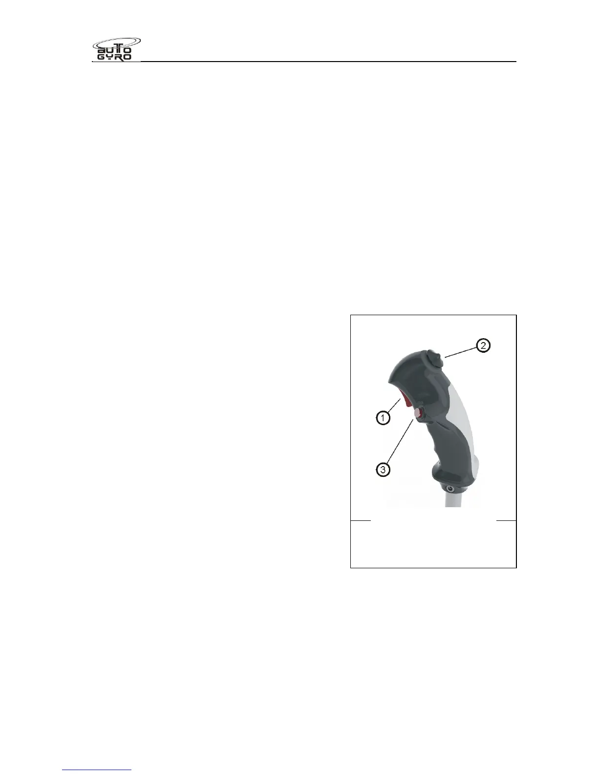
The control stick head is ergonomically shaped to
fit the pilot’s right hand and features control buttons
for radio transmission (1), a four-way trim function
(2), and activation of the pre-rotator (3).
The trim control works as a classical 4-way beep
switch. Pulling the beep switch back increases aft
trim or nose-up tendency, while pushing the switch
forward reduces back trim pressure, leading to a
nose-down tendency. Roll trim is effected by
pushing the trim switch to the respective side.
Because of a safety circuit, activation of the pre-rotator is only possible with the pneumatic
mode selector in FLIGHT position and the control stick fully forward. This prevents
inadvertent activation of the pre-rotator during flight or in BRAKE mode.
The LH flight controls must never be restricted by passenger or objects. Passengers must
be briefed.
Rudder and front wheel control
The rudder is connected to adjustable foot pedals with steel cables which are routed
through the lower fuselage and inside the keel tube. Both pairs of pedals are