SYSTEM DESCRIPTION
RSUK0287_POH_Cavalon Revision 3., Issue Date 06.04.16 7-8
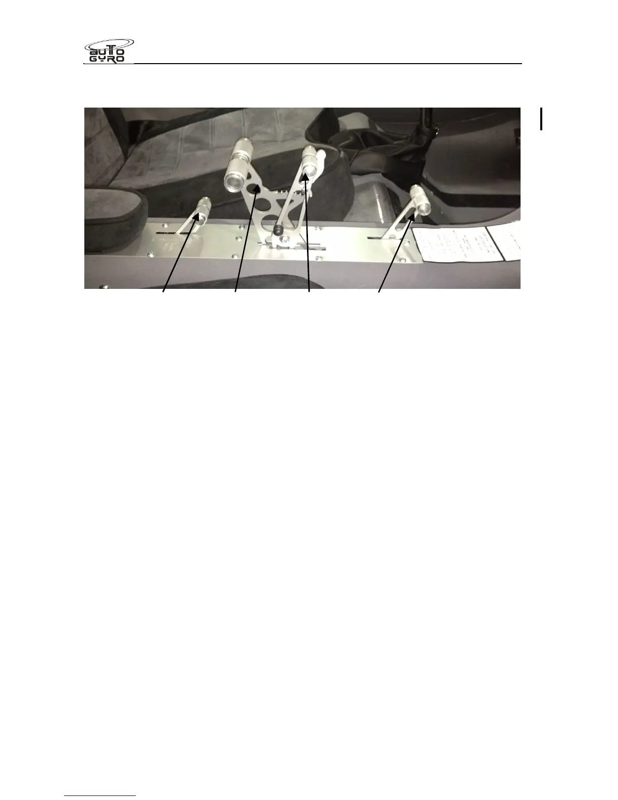
The quadrant also features the control for cabin heating / air conditioning system (4). All
controls are labelled correspondingly by engraved text and symbols on the cover plate.
Heater control (4) Throttle (1) Brake lever (2) Choke (3)
7.11 Electrical System
The 12V DC electrical system consists of an engine driven electrical generator, a battery,
master switch, indicators, switches, electrical consumers, and cabling. With the ROTAX 914
UL engine an electrical power supply is vital for continued engine operation as this engine
variant solely relies on electrically driven fuel pumps.
Turning the master switch to the ON position closes the battery contact and energizes the
gyroplane’s electrical system. The red LOW VOLT warning light will illuminate briefly as a
functional check. A steady indication, however, warns the pilot that the voltage of the
system has dropped below a safe value. In this case a safety circuit (load shedding relay)
will automatically disable the aircraft lights and the 12V power receptacle. This is often the
case when turning the keyswitch on, and the lamp should extinguish once the engine is
running and the regulator supplying sufficient electrical energy to meet demand.
A red GEN warning light is installed to indicate that the battery is not being charged.
Turning the keyswitch on (if fitted with a 914UL engine) will also energise the regulator
relay, and provide electrical energy from the battery to the primary electrical fuel pump. This
relay is to protect the engine fuel supply in the event of a cabin primary fuse failure, or a
battery short circuit, enabling engine fuel supply to continue in those circumstances.
Seat heating note. The optional seat heat is actuated by depressing the rocker switch
between the seats to either (I) or (II) heat setting (with the switch centred for OFF). The
heater element is self regulating to that setting. The seat heating requires considerable
energy, and is recommended to be left OFF (or at least reduced to heat setting (I)), once the
cabin heater and cabin is up to temperature (around 5 minutes).
Note that the seat heating elements will only work when the LOW VOLT warning LED is
OFF, being automatically disconnected when the voltage falls below the LOW VOLT relay
threshold.
Warning! High electrical load in flight with low engine rpm may reduce the ability of the
charging circuit to replenish the battery, thereby reducing the battery reserve in the event of
a charging circuit failure. Illumination of the LOW VOLT warning lamp lights demonstrates