SYSTEM DESCRIPTION
RSUK0287_POH_Cavalon Revision 3., Issue Date 06.04.16 7-1
SYSTEM DESCRIPTION
SECTION 7 -
7.1 Introduction
This section contains the description of the gyroplane and its standard systems and
equipment. Optional equipment is described in Chapter 9 of this manual.
7.2 Airframe and Undercarriage
The load carrying structure of the gyroplane consists of a composite monocoque occupant
enclosure which is connected to the rotor tower and keel tube. The composite structure,
tower and aft extension carries all loads induced by the crew stations, engine, rotor,
undercarriage, stabilizer, and serves as installation platform for additional equipment.
Stabilizer structure with rudder is made of GRP (or in certain cases CRP) and is bolted to
the aft extension of the main frame. Attachment points for the engine installation are
provided by a steel tube ring mount at the rear of the firewall.
The landing gear consists of a steerable nose wheel in a steel fork and two main wheels
with hydraulic brake system. Both main wheels are equipped with wheel spats made from
GRP and are mounted to the ends of the spring spar, which is made from GRP. The spar is
designed to absorb even higher than normal landing loads in case of a hard landing or
crash.
7.3 Doors, Windows and Exits
This gyroplane features one large undivided glazed canopy and two hinged doors with
locking mechanism at the left hand and right hand side. The locking mechanism can be
operated from the inside and outside by moving an aluminium locking lever. The door is
properly locked when the lever jumps sidewise into its locking detent.
Two adjustable fresh air vents one on each side and one sliding window per side with
pivoting vent are provided for ventilation. The sliding window can be used as viewing hatch
in case of emergencies and is wide enough to reach through with a hand.
The gyroplane is embarked and disembarked from each side while the doors are held open
by a gas spring. In case of emergency the opposite door may have to be used to disembark
the aircraft.
7.4 Fuel System
The fuel system consists of two tanks permanently
connected with a large bore crossover tube allowing
them to be considered as one large tank, with a single
filler port, fuel and ventilation lines, fuel level indicator,
and water drain point. The filler port is located at the
left hand side of the gyroplane. In order to open the
filler cap, lift, then turn the flap, and pull out. Reverse to
close cap. The cap is retained to the aircraft via a
security cable.
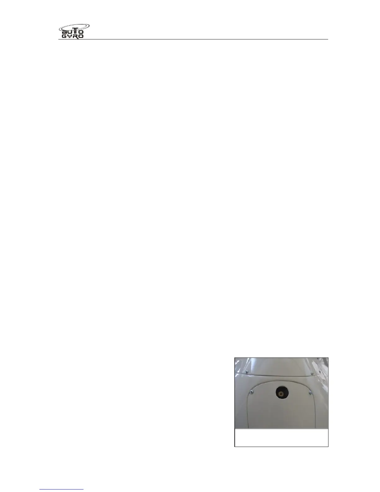
The tanks are installed behind the seats and have a
capacity of 100 usable litres. Fuel level can be checked
Under body water drain
Valve