SYSTEM DESCRIPTION
RSUK0287_POH_Cavalon Revision 3., Issue Date 06.04.16 7-9
that the electrical system voltage has dropped below 12v, and, provided the charging circuit
is working, that the electrical demand has exceeded supply. If lit, or intermittently lit, either
reduce the electrical load or increase generator circuit output by increasing the engine rpm,
as safe or appropriate to do, such that the lamp remains off.’
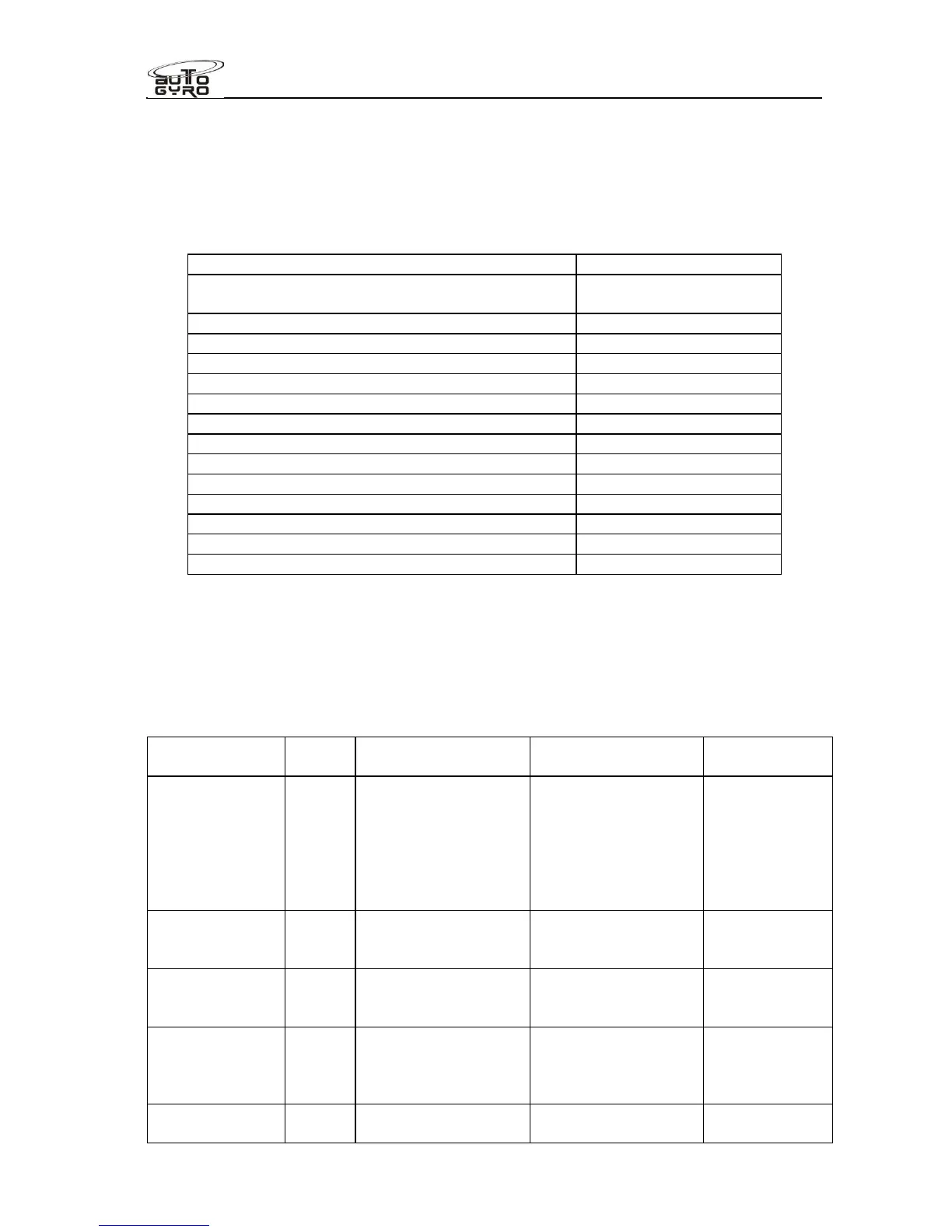
The power consumption of individual equipment is listed in the following table:
Generator maximum (see Rotax handbook for
output curve v engine RPM)
(-) 240 W
Electrical fuel pump 21 W
Pneumatic compressor 124 W (peak) / 103 W
Engine cooling fan 194 W (peak) / 97 W
Seat heating 86W/seat peak
Cabin heat blower fan 32 W
Strobe lights 28 W
NAV lights (LED) 9 W
Landing light (LED) 10 W
Radio ATR500 2 W (rcv) / 35 W (xmt)
Radio ATR833 7 W (rcv ) / 35 W (xmt)
ATC Transponder TRT800H max. 10 W
Ipad 12 W
7.12 Lighting System
The aircraft is approved for day VFR operation only. Position lights, landing light and
strobes are available as optional equipment. If installed, refer to SECTION 9 of this manual.
7.13 Electrical circuit protection
Fuse
description
Rating Protects Fuse type
Location
Main incoming
supply to
cockpit
40A Main positive supply
is fed to the starter
solenoid from the
battery. The supply
continues then
through the 30amp
fuse to the cabin.
Bolt in strip type,
MTA S.p.A.
“Midival” range
30A rating
Engine bay
fuse box, left
side within
inner firewall
Compressor 10A Only supplies the
pneumatic
compressor
CB Inst. Panel
Regulator relay
(914UL engine
variant only)
1A Regulator Relay
circuit
CB Inst. Panel
Primary fuel
pump (914UL
engine variant
only)
5A Fuel pump P1 Blade fuse Near fuel
pump in pump
harness
Secondary fuel
pump
5A Fuel pump P2 CB Inst. Panel