RotorSport logo
Flight Manual
Cavalon
SECTION 8
HANDLING / MAINTENANCE
RSUK0287_POH_Cavalon Revision 3.0, Issue Date 06.04.16 8-9
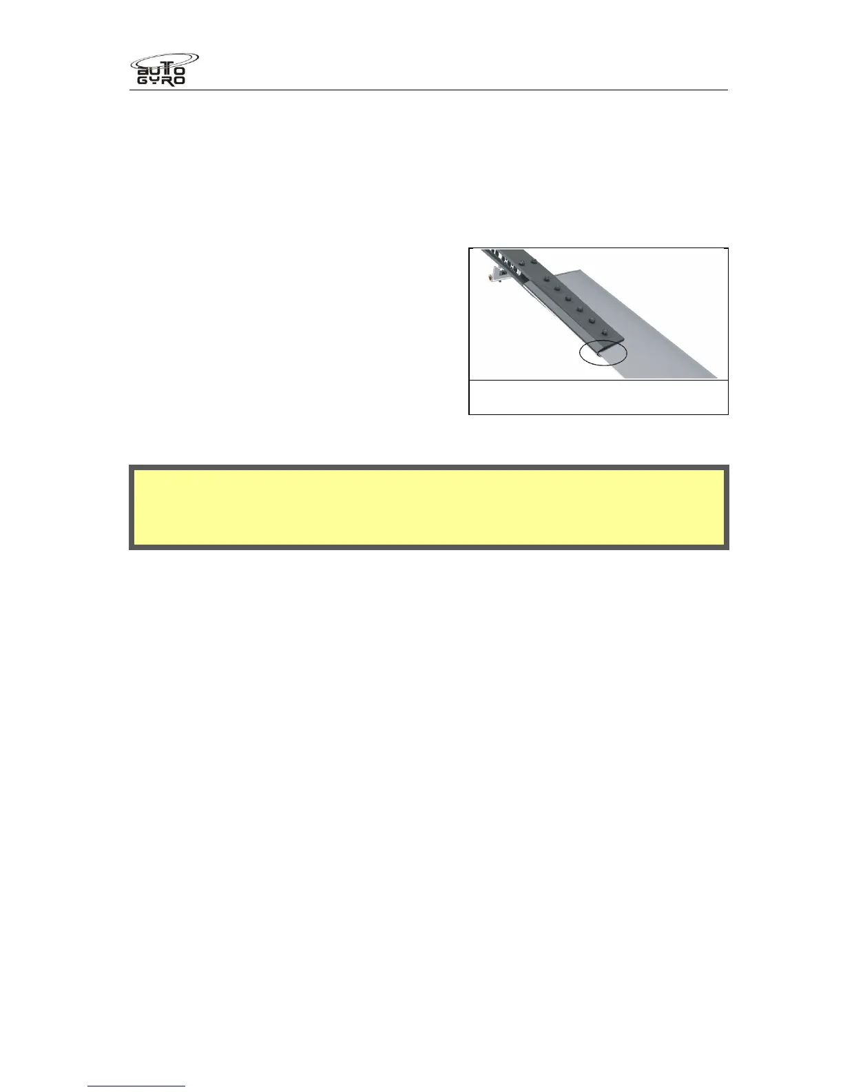
1. The rotor blades, clamping profile and rotor hub are labelled with an engraved serial
number.
2. Insert the first rotor blade carefully into the clamping profile. Make sure that all serial
numbers match.
3. Fit the rotor hub side with the according serial number to clamping profile and blade.
Insert fitting bolts without using force so that the bolt end is on top when the rotor
system is installed. For re-identification and correct installation position the shaft
length is provided in the figure above. Example: 40/12 means shaft length 40mm.
4. Position the washers and the locknut and
hand-tighten all nuts.
5. Torque-tighten nuts with 25 Nm from the
inside to the outside, using a torque
wrench. When doing so, counter-hold bolts
to prevent any damage the hub and blade
holes.
6. Repeat steps 2 to 5 for the second rotor
blade.
8.15.4 Installation of the Rotor System
CAUTION
During installation make sure to have each and every part of the rotor system
installed in exactly the same way and orientation as it was before.
1. Secure the gyroplane on level ground by engaging parking brake, adjust the rotor
head or teeter tower corresponding to 30deg from fore-aft and pressurize the rotor
brake up to maximum. Secure a step ladder to the right side of the aircraft.
2. Check correct matching of parts: The rotor hub and the teeter tower are marked with
two dots according to the orientation for installation.
3. Lift the rotor blade with a second briefed person (standing either side of the aircraft).
4. Approach with the rotor system from the side to the gyroplane and make sure not to
collide with propeller or stabilizer The person fitting the rotor to the aircraft has the hub
bar on his shoulder, and climbs the ladder with the rotor across the aircraft. The rotor
is then lifted over the teeter tower and lowered into place.
5. The second person can let go, as soon as it is resting centrally in the teeter tower on
the teeter stops.
6. Insert teeter bolt by hand in the same orientation as it was before (bolt head should be
at that side of the teeter block which is marked with one dot) while matching the shim
washers with the corresponding installation positions.
7. Check direction of assembly and shim washers: rotor hub, teeter tower and shim
washers are marked on each side either with one or two engraved dots.
8. If the teeter bolt cannot be inserted, tilt the rotor blade along the teeter axis with the
free hand.
9. Install washer and castellated nut. Hand-tighten only, 1-2Nm, and secure with a new
split pin. Use split pins only once. Make sure that the teeter bolt can be turned easily
by hand.
10. Check that the rotor teeters freely to the teeter stops, and grease the hub block
grease nipple. Turn the rotor fore/aft and fit tie down bag to secure the rotor.
Position where serial numbers are
engraved (bottom side)


 To Next Page