RotorSport logo
Flight Manual
Cavalon
SECTION 8
HANDLING / MAINTENANCE
RSUK0287_POH_Cavalon Revision 3.0, Issue Date 06.04.16 8-8
CAUTION
Cavalon is approved only with RotorSystem II ROA or TOPP. The RAO rotor
has a reduced blade angle of attack, as is easily notable by using black blade to
hub clamping profiles, and red end caps. The TOPP rotor has clear anodised
(silver) spacers and blue end caps.
CAUTION
The assembled rotor system can be damaged irreparably if handled incorrectly.
If the rotor system is lifted in a wrong way, its own weight may overstrain the
material.
8.15.2 Disassembly of the Rotor System
1. To disassemble the rotor system, place it upside down onto a clean surface or stands
to support the rotor at approximately 2 m from the hub.
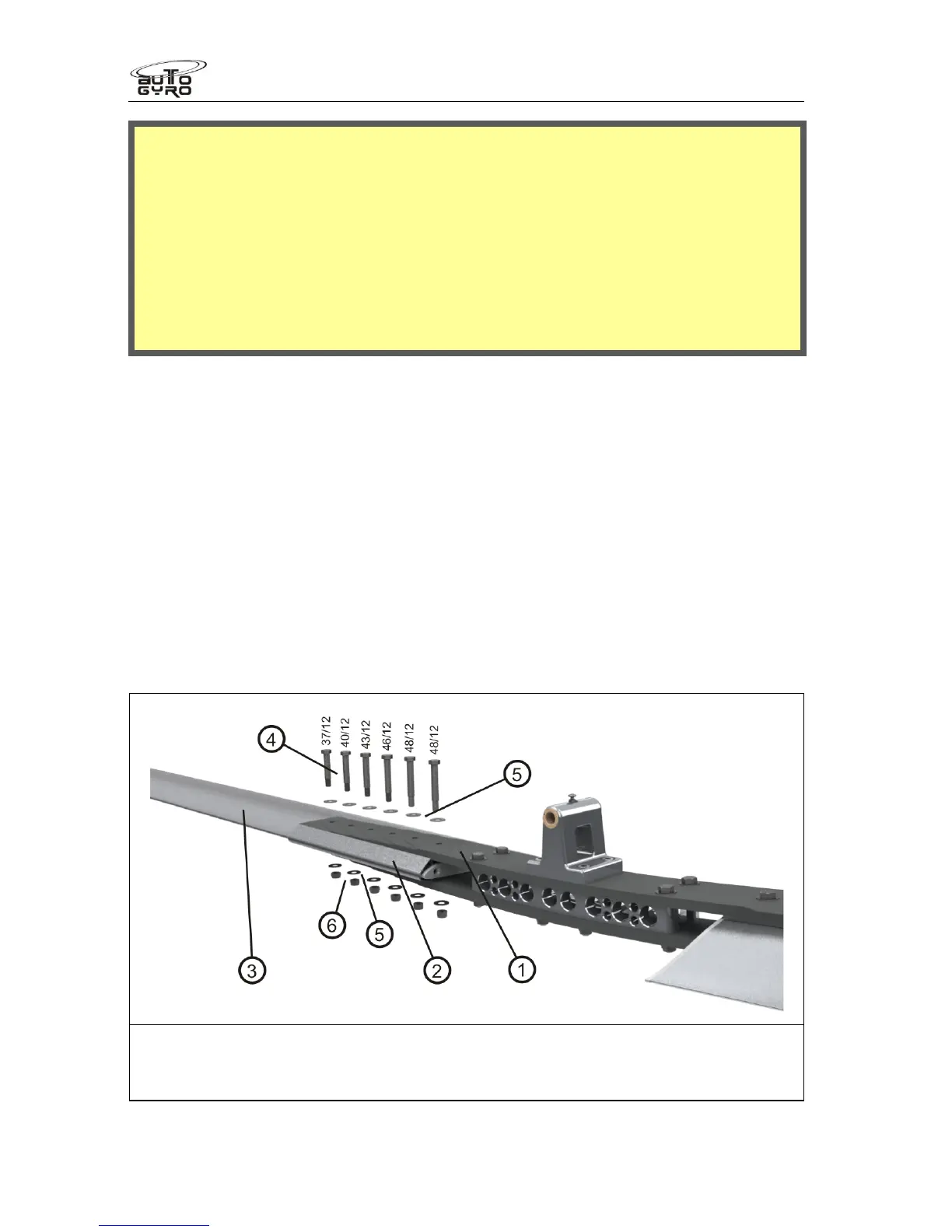
2. Loosen locknuts (6) on the first blade by counter holding the corresponding bolt head
to prevent it from turning inside the blade holes.
3. Push out all fitting bolts (4) without any force, but use no more than a gentle tapping if
necessary. Tilt the rotor blade up and down to support easy removal of the bolt.
Note that fitting bolts have different shaft length.
4. Carefully pull the rotor blade out of the hub (1) in radial direction and take off the
clamping profile (2).
5. Repeat step 2 to 4 on second rotor blade.
6.
Do not disassemble the rotor hub!
7. Store and transport rotor blades, clamping profile and rotor hub only in b or using
other suitable means to prevent bending or surface damage.
1 – Rotor hub 4 – Fitting bolts (as depicted)
2 – Clamping profile (BLACK Colour) 5 – Washer (12 ea.)
3 – Rotor blade 6 – Lock nuts (6 ea.)
8.15.3 Assembly of the Rotor System