SYSTEM DESCRIPTION
RSUK0287_POH_Cavalon Revision 3., Issue Date 06.04.16 7-4
7.6 Power Plant
Engine
There are two engine variants available, being the ROTAX 912 ULS normally aspirated
reciprocating engine and the ROTAX 914 UL turbo charged version. Both engine types are
4 cylinder, horizontally opposed, 4 stroke engines.
The ROTAX 912 ULS engine provides a maximum take-off power of 100 horse power while
the turbo charged version offers a maximum take-off power of 115 horse power. For
technical details refer to the engine manufacturer’s manual.
Oil system
The oil reservoir with dipstick is accessed through a cover on the left hand side of the
fuselage. The cover is held by 3 cam lock fasteners which can be locked or unlocked by a
quarter turn. The type of lubrication system requires a special procedure for accurate oil
level checking and to prevent overfilling, which is described in SECTION 8 of this manual.
Engine cooling
Engine cooling is provided by ram air cooled cylinders and liquid cooled cylinder heads.
Therefore, cylinder head temperature (CHT) indication in the cockpit corresponds to water
temperature. Sufficient cooling air flow is provided by a ram air duct. The water cooling
system comprises of engine driven pump, radiator with thermo-activated electrical blower
fan, expansion tank with radiator cap, overflow bottle, and hoses.
A single, large area radiator is mounted above the engine so that cooling air from the ram
air duct passes through the cooler, is directed around the engine’s cylinders, and finally
escapes through an opening at the lower rear end of the engine cowling. Force cooling is
ensured by an electrically driven ducted fan controlled by a thermo switch. A push button in
the cockpit allows manual activation temporarily which is typically used to avoid possible
heat build-up after shut-down.
In order to support natural heat circulation (chimney effect) the blower fan reverses in
ground mode to allow the hot air escape at the ram air opening in the forward mast cover.
Ground mode is detected when the engine is off.
For the relevant checking and replenishing procedures, refer to SECTION 8 of this manual
and also the engine manufacturer’s manual.
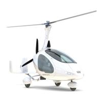
7.7 Propeller
A three-bladed, fixed pitch propeller with aluminium hub is used as standard version. The
propeller blades are made from composite material with a foam core.
7.8 Rotor System
The two-bladed, semi-rigid, teetering rotor system comprises high-strength aluminium
extruded rotor blades, a hub bar, and a common teeter hinge assembly.
The rotor blades feature an aerodynamic profile especially suitable for rotorcraft which, in
combination with its relative centre of gravity, provides aerodynamic stability by eliminating
negative blade pitching moments and flutter tendency. The hollow blade profile is closed at
both ends by plastic blade caps.
The aluminium rotor hub bar is pre-coned to the natural coning angle of the blades and
connects the blades firmly to each side using 6 fitting bolts and a clamping profile. In order