Calidus
SYSTEM DESCRIPTION
AutoGyro_POH_Calidus Revision 4.0 – Issue Date 17.JAN.2019 7-1
SECTION 7 - SYSTEM DESCRIPTION
7.1 Introduction
This section contains the description of the gyroplane and its standard systems and
equipment. Optional equipment is described in Chapter 9 of this manual.
7.2 Airframe and Undercarriage
The load carrying structure of the gyroplane consists of a composite monocoque occupant
enclosure, bolted to an inert-gas welded stainless steel tube framework including tower and
aft extension. The composite structure and main frame carries all loads induced by the crew
stations, engine, rotor, undercarriage, stabilizer, and serves as installation platform for
additional equipment.
Stabilizer structure with rudder is made of GRP (or in certain cases CRP) and is bolted to
the aft extension of the main frame. Attachment points for the engine installation are
provided by a steel tube ring mount at the rear of the mast, which also supports the rotor at
its top end.
The landing gear consists of a steerable nose wheel in a steel fork and two main wheels
with hydraulic brake system. Both main wheels can be equipped with wheel spats made
from GRP and are mounted to the ends of the spring spar, which is made from GRP. The
spar is designed to absorb even higher than normal landing loads in case of a hard landing
or crash.
7.3 Doors, Windows and Exits
This gyroplane features one large undivided plexiglass canopy which is hinged at its left
hand side and has a locking mechanism on the right hand side. The locking mechanism can
be operated from the inside and outside by lifting the operating lever. The canopy is
properly locked when the detent interlocks with the locking pin bushing and the lever is
parallel to the canopy frame. Note that a firm force is needed to ensure the detent interlocks
fully in order to lock the canopy properly.
Two adjustable fresh air vents on the right hand side and one sliding window with pivoting
vent are provided for ventilation. The sliding window can be used as viewing hatch in case
of emergencies and is wide enough to reach through with a hand.
The gyroplane is embarked and disembarked from the right hand side while the canopy is
held open by a restraint strap. In case the canopy cannot be opened, use the emergency
hammer located at the left hand side of the pilot station to break the Plexiglas and evacuate.
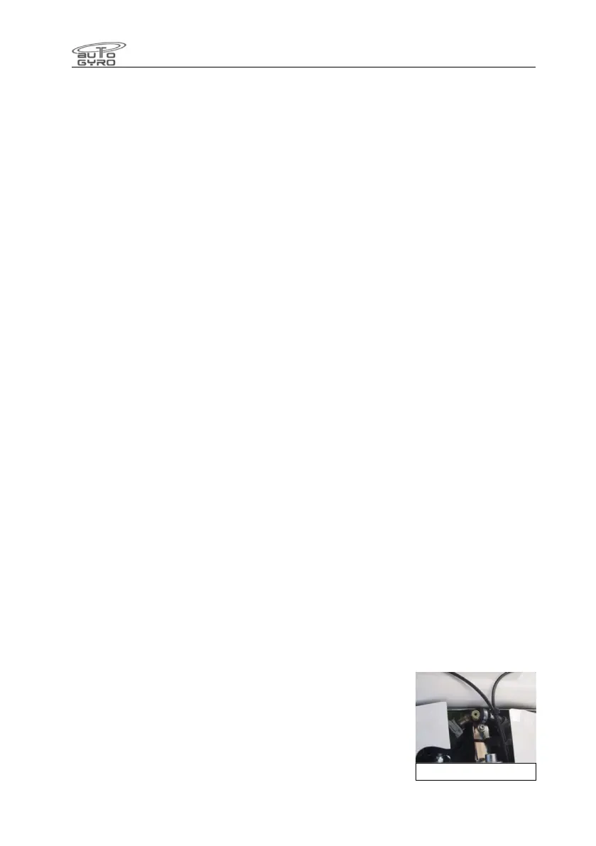
7.4 Fuel System
The fuel system consists of one or two tanks, a single filler
port, fuel and ventilation lines, fuel level indication system, and
drain. The filler port is located at the left hand side of the
gyroplane. In order to open the (optionally lockable) filler cap,
lift, then turn the flap, and pull out. Reverse to close cap. The
cap is optionally retained to the aircraft via a security cable.
This cable is deleted in later aircraft, because the risk to fly with
Drain Valve