HIRO Installation Manual GDO-12V1
15
© Copyright 2019
6.7 Safety Testing & Accessories
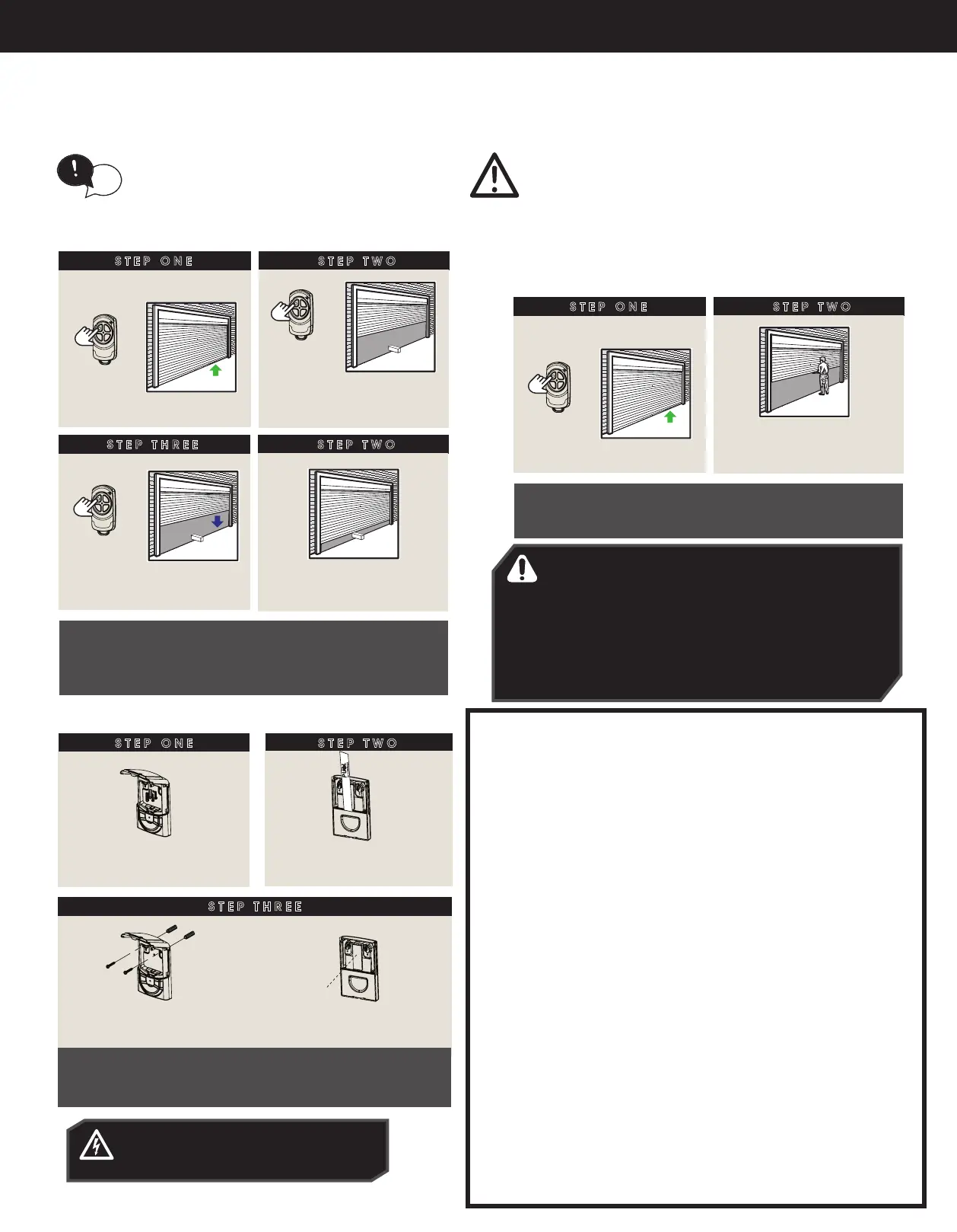
6.7.1 Testing the Close Cycle
STEP ONE
STEP TWO
IF THE DOOR DOES NOT PROPERLY REVERSE:
Check that the close limit position is where the door
touches the ground. If the door STOPS but does not
reverse, decrease the force pressure.
Press to open door halfway
when the door is closed
Place a piece of 2” x 4”
timber laid at in centre
of opening
STEP THREE
STEP TWO
When door contacts
object, the door must
STOP and REVERSE!
to close
to stop
CAUTION: Take care when testing the safety obstruction force.
Excessive force may cause serious personal injury and/or property
damage can result from failure to follow this warning.
ATTENTION: Testez la résistance aux obstacles avec précaution.
Une force excessive présente un risque de blessure corporelle
grave et/ou d’endommager le matériel si vous ne respectez pas
cet avertissement.
6.7.2 Testing the Open Cycle
STEP ONE
STEP TWO
IF THE DOOR DOES NOT STOP: The Force pressure
may be excessive and need adjusting. Follow steps to
decrease force pressure.
Press to open door
when the door is closed
When the door reaches
halfway, grab the bottom
rail rmly. Door should STOP!
IMPORTANT WARNING! If the door is closing and is
unable to re-open when obstructed, discontinue use. Do
not use a door with faulty obstruction sensing. Repair
fault and re-test before using.
AVERTISSEMENT IMPORTANT! Si la porte est en train
de se refermer et ne peut pas être rouverte, arrêtez de
l’utiliser. N’utilisez pas une porte dont les détecteurs
d’obstacles sont défectueux. Réparez-les et refaites un
essai.
(Appendix A)
(Appendix A)
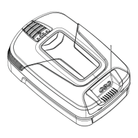
6.7.3 Installation of Premium Wall Control
ELECTROCUTION! Be mindful not to drill
into existing wiring as this may result in
serious harm and or death.
STEP THREE
Pre-drill holes, using
6mm drill bits
Mount at least 5 feet off the ground, and make sure
the door is visible from this location.
Follow the instructions on how to set transmitter
codes in next section.
Place velcro on
back of cover
OR
STEP ONE
Remove the mounting
hardware from inside cover
Pull the battery tab to
commission
STEP TWO
INSTALL (US) WALL MOUNTED TRANSMITTER
IMPORTANT WARNING
LOCATE THE WALL MOUNTED REMOTE CONTROL:
(1) WITHIN SIGHT OF DOOR.
(2) AT MINIMUM HEIGHT OF 5 FEET ABOVE FLOORS, LANDINGS,
STEPS OR OTHER ADJACENT WALKING SURFACE SO SHALL
CHILDREN ARE NOT ABLE TO REACH IT, AND
(3) AWAY FROM MOVING PARTS OF THE DOOR.
(4) PLACE THE ATTACHED ENTRAPMENT WARNING LABEL ON WALL
NEXT TO WALL MOUNTED TRANSMITTER. USE AN ADDITIONAL
MECHANICAL MEANS (PLATE, BOARD, ETC.), WHICH CAN
SECURE THE LABELS TO SURFACES TO WHICH THE ADHESIVE
WILL NOT ADHERE.
(5) DO NOT REMOVE OR PAINT OVER THIS LABEL.
PLACEZ LA TÉLÉCOMMANDE MURALE:
(1) EN VUE DE LA PORTE.
(2) À UNE HAUTEUR D’AU MOINS 1,50M (5PIEDS) AU-DESSUS DU
SOL, DU PERRON, DES MARCHES, ETC. AFIN QUE LES PETITS
ENFANTS NE PUISSENT PAS L’ATTEINDRE,
(3) ET À DISTANCE DES ÉLÉMENTS MOBILES DE LA PORTE.
(4) PLACEZ L’ÉTIQUETTE AVERTISSANT DU RISQUE DE SE FAIRE
PIÉGER SUR LE MUR À PROXIMITÉ DE L’ÉMETTEUR. UTILISEZ UN
SUPPORT PHYSIQUE SUPPLÉMENTAIRE (PLAQUE, PANNEAU,
ETC.) PERMETTANT DE FIXER LES ÉTIQUETTES SI ELLES
N’ADHÈRENT PAS À LA SURFACE DU MUR.
(5) CETTE ÉTIQUETTE NE DOIT PAS ÊTRE RETIRÉE NI PEINTE.
HELPFUL TIP: To conduct safety testing with ease
precode a remote control button first. Refer to
coding transmitters in next section.
tip