Power Supply
Properly earthed 3 pin single -phase power is required.
a.
WARNING! A portable power generator is
not recommended due to spikes, surges and
fluctuations in the supply.
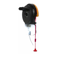
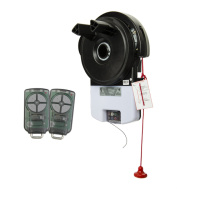
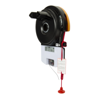
Kit Contents of GDO-8V3
1. 1 x GDO-8 Shed Master
®
drive unit
2. 2 x Locking bar covers
3. 2 x Transmitters with batteries
Not included in some models are;
4. 1 x Weight Bar
5. 2 x Nilock Hex nut M4
6. 2 x Flat washer I.D. 3/16” x 1/2”
7. 2 x Pan head screw M4x50mm
Unsuitable Door Types
The drive must not be used with a door incorporating
a wicket door, unless the drive cannot be operated
with the wicket door open The fitting of an opener to
doors with removable mullions is not recommended
Sideroom
The minimum sideroom required from the edge of the
door curtain is 40mm to the inside of the door bracket,
and 85mm to the wall. If a Battery Backup is to be fitted,
at least 135mm to the bracket is required.
Therefore the recommended sideroom from the edge
of the door curtain is 135mm to the inside of the door
brachet, and 175mm to the wall as per diagram.
85
40
175
135
Minimum Side room Recommended Side room
WARNING!
• The door may operate unexpectedly, therefore do not allow anything to stay in the path of
the door.
• When operating the manual release while the door is open, the door may fall rapidly due
to weak or broken springs, or due to being improperly balanced.
• The drive must not be used with a door incorporating a wicket door, unless the drive cannot
be operated with the wicket door open.
• The drive is intended to be installed at least 2.5m above the floor.
• Do not disengage the opener to manual operation with children/persons or any objects
including motor vehicles within the doorway.
• If the door is closing and is unable to re-open when obstructed, discontinue use. Do not
use a door with faulty obstruction sensing
• When using auto close mode, a Safety beam must be fitted correctly and tested for
operation at regular intervals. Extreme caution is recommended when using auto close
mode. All safety rules must be followed.
ELECTROCUTION!
• Place opener in protected area so that it does not get wet.
• Do not spray with water .
• Disconnect the power cord from mains power before making any repairs or removing
covers. Only experienced service personnel should remove covers from the opener.
• If the power supply cord is damaged, it must be replaced by an Automatic Technology
service agent or suitably qualified person.
• Connect the opener to a properly earthed general purpose 240V mains power outlet
installed by a qualified electrical contractor.
CAUTION:
Emergency Access • If garage has no pedestrian entrance door, an emergency access device should be
installed. This accessory allows manual operation of the garage door from outside in case
of power failure.
Muscular strain • Practice correct lifting techniques (carton weighs approx 9kgs)
• Practice correct lifiting techniques when required to lift the door as per installation instructions.
Fall from ladder • Ensure ladder is the correct type for job.
• Ensure ladder is on flat ground.
• Ensure user has 3 points of contact while on ladder.
Crush injury from
unsecured door
• Place a 2 metre exclusion zone around area under the door while it is unsecured.
• Do not move under door while on door support (or ladder)
• Follow the installation instructions
• Fit door support (or ladder) snugly under door before removing bracket.
• Ensure door support (or ladder) is on flat ground
Garage Door • Examine the door installation, in particular springs and mountings for signs of wear, damage
and imbalance.
• The garage door must be well balanced. Sticking or binding doors must be repaired by a
qualified garage door installer prior to installation of the opener.
• Remove or disengage all garage door locks and mechanisms prior to installation of the
opener.
• Ensure the U-bolt on the opposite end to the motor is tight.
Entanglement • Never plug in and operate opener prior to installation.
• Keep hands and loose clothing clear of door and guides at all times.
Entrapment under
operating door
• DO NOT operate the opener unless the garage door is in full view and free from objects
such as cars and children/people. Make sure that the door has finished moving before
entering or leaving the garage
• In order for the opener to sense an object obstructing the door way, some force must be
exerted on the object. As a result the object, door and/or person may suffer damage or
injury.
• Ensure the garage door is in good working order by undertaking regular servicing.
• Install the optional wall transmitter in a location where the garage door is visible, but out
of the reach of children at a height of at least 1.5m.
• Safety beams must be installed if the closing force at the bottom edge of the door exceeds
400N (40kg)
This automatic garage door opener is designed and tested to offer safe service provided it is
installed and operated in strict accordance with the following safety rules. Failure to comply with
the following instructions may result in death, serious personal injury or property damage.
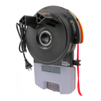
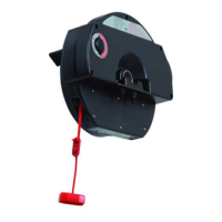
Position
The opener can be installed on either the right - or left hand side of the
door (when viewed from the inside the garage). The opener is factory
set for right hand side installation.
The opener must be installed in a dry position that is protected from
the weather. Moisture or corrosion damage is not covered by the
Warranty.
• Screwdrivers
• Marker Pen
• Door Stand
Symptom Possible cause Remedy
The opener does
not work from the
transmitter
Garage door in poor condition e.g. springs may
be broken
The opener does not have power
The battery in the transmitter is flat
Transmitter does not contain TrioCode 128
Technology
The opener has been put into “Vacation Mode”
The transmitter button is not programmed to
operate the door.
Door Code LED is flashing yet the opener is not
working.
Check the door’s operation
Plug a device of similar voltage (e.g. a hairdryer) into the
power point and check that it is OK
Replace the battery
Check the transmitter has grey buttons and the model number
should display V2. Contact dealer for support if otherwise.
Turn off “Vacation Mode”
Coding the transmitter
Ensure the correct button on the transmitter is being pressed.
One transmitter works
but the other/s do not
Faulty transmitter
Flat battery
Replace transmitter
Replace battery
The door does not
work from transmitter
or operate button
The opener is disengaged Re-engage the opener
The transmitter range
varies or is restricted
Variations are normal depending on conditions
e.g. temperature or external interference
The battery life is exhausted
Position of the transmitter in the motor vehicle
Make sure you can see the door when you use the transmitter.
Check the battery status by pressing a button (flashing or no
light requires battery to be changed)
Aim the transmitter through the windscreen.
The door reverses for
no apparent reason
This may occur occasionally from environmental
conditions such as areas that are windy, dusty or
have extreme temperature changes.
If Safety beams are installed they may be partially
obstructed.
Ensure the door runs smoothly before increasing the force
pressure.
Ensure the beam path is not obstructed. Check the Alignment.
Auto Close not
working
Safety Beam or wiring faulty Repair Safety Beam or replace wiring.
Re-align optics. See Safety Beam instructions.
The door stops or
moves very slowly
under battery
(Optional Battery Back
Up Accessory)
The batteries may have little to no charge Connect mains power and leave the batteries to charge. The
batteries may take 24 to 48 hours to reach their maximum
charge capacity.
The SERVICE LED has
started to flash and
is beeping numerous
times
A Fault has been detected. The fault will be
active each time an attempt is made to operate
the door.
Record opener function (How many beeps?) then press the
SET button once to reset the opener. If the fault continues to
be tripped contact 1300 736 410 for support.
The Open (Green)
LED and Close (Red)
LED are flashing
alternatively
Opener is overloaded Check the doors operation by disengaging the motor and
ensuring the door runs smoothly. If necessary make door
adjustments or contact your door professional.
The Open (Green) LED
continues to flash
Door obstructed when opening Clear away any obstructions and test door opens correctly.
(If door is damaged, contact your door professionl).
The Close (Red) LED
continues to flash
Door obstructed when closing
Limits may be cleared
Clear away any obstructions and test door closes correctly.
(If door is damaged, contact your door professional).
Remove all power sources (including the battery backup). Wait
till all lights are out (10-15 secs), then reconnect power. If Red
LED is flashing, limits are not set. Reset Limits.
Troubleshooting Guide
6 - 8 Fiveways Boulevard, Keysborough, VIC, Australia 3173 ABN 11 007 125 368
P: 1300 133 944 E: sales@automatictechnology.com.au W: www.automatictechnology.com.au
WARNING!
Take care when testing or adjusting the
Safety Obstruction Force. Excessive force may cause
SERIOUS PERSONAL INJURY and/or PROPERTY
DAMAGE.
Testing Close Cycle
a.
Press the programmed transmitter to open the door.
b.
Place a piece of timber approximately 40mm high on the floor
directly under the door.
c.
Press the programmed transmitter to close door.
d.
The door should strike the object and re-open.
Testing Open Cycle
e.
Press the transmitter to close the door.
f.
Press again to open the door.
g.
When the door reaches approximately half way, firmly grab the
door’s bottom rail - the door should stop.
h.
If the door does not reverse readily when closing, or stop when
opening, the force may be excessive and need adjusting.
40mm block of wood
Safety Obstruction Forces
WARNING!
If the door fails these tests, put the
opener into manual mode, only operate the door
by hand and call for service.
WARNING!
Photo electric beams must be
installed if the closing force at the bottom edge of
the door exceeds 400N (40kg) force.
WARNING!
Please test the manual release
mechanism to ensure that the manual release is
easy to operate. No more than 15 kg of force
should be required to disengage the door using
the manual release cord. If excessive force is
required reset the close limit position.
To Recall Factory Set Force
a.
While holding down the FORCE MARGIN SET button, press the
SET button for two (2) seconds.
b.
Release both buttons. The default setting should now be recalled.
To Recalculate Force Margins
a.
Press and hold the SET Button for two (2) seconds, the beeper will sound once.
b.
The door will start to move and re-calculate force margins. The door can move between the open and close limit
positions up to four (4) times (depending on the position of the door and the power up condition).
c.
A single beep will be heard once the process is complete.
d.
Test the force again as per Testing Close Cycle and Testing Open Cycle.
Adjusting Safety Obstruction Force
The Safety Obstruction Force is calculated automatically during setup.
Adjusting this is normally only necessitated by environmental conditions
such as windy or dusty areas, and areas with extreme temperature
changes.
To Adjust Force Pressure
a.
Hold down FORCE MARGIN SET button.
b.
While holding the FORCE MARGIN SET button, press the;
i.
To Increase:
PLUS
(+) / OPEN button. Each press increases the force margin.
ii.
To Decrease:
MINUS
(-) / CLOSE button. Each press decreases the force margin.
c.
The Open / CLOSE Limit LED will flash each time the PLUS (+) / OPEN or MINUS (-) / CLOSE button is pressed to indicate a force
increase / decrease.
d.
If either (OPEN / CLOSE) Limit LED is on continuously when pressing the PLUS (+) / OPEN or MINUS (-) / CLOSE button, this
indicates that the maximum setting has been reached.
e.
Test the force again as per Testing Close Cycle and Testing Open Cycle.
GDO-6
GDO-8
GDO-8
GDO-8
GDO-6
GDO-6
Important Note:
Only TrioCode
TM
128 Technology Transmitters
and Keypads are compatible with these
GDO-6V4 and GDO-8V3 products.