6
MegaCode
®
Receiver Installation Instructions
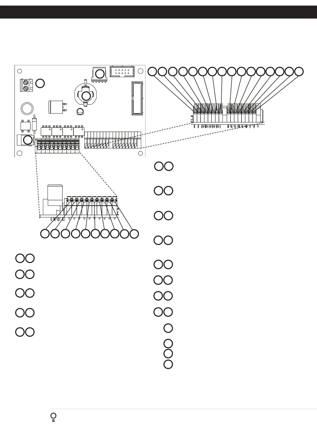
AC/DC Power Supply Input 12 to 24 AC/DC power
supply input terminal.
Output One (1) normally open contacts of the solid
state relay output can be controlled by remote control
transmitters, wired inputs and a programmable time clock.
Output Two (2) normally open contacts of the solid
state relay output can be controlled by remote control
transmitters, wired inputs and a programmable time clock.
Output Three (3) normally open contacts of the solid
state relay output can be controlled by remote control
transmitters, wired inputs and a programmable time clock.
Output Four (4) normally open contacts of the solid
state relay output can be controlled by remote control
transmitters, wired inputs and a programmable time clock.
13
01 02
03 04
05
06
07 08
09 10
11
12
27
14
15
16
17 18
19 20
21
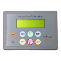
2. Operating Controls
Fig 2.1
1816 171512 13 1411 2624 252320 21 2219
28
29
30
27
2423
25
22
26
28
29
30
0806 070502 03 0401
1009
Trigger Input One (1) the output one (1) can
also be controlled via trigger one (1) independently.
The trigger input can be programmed to activate its output similar
to a transmitter button.
Trigger Input Two (2) the output two (2) can
also be controlled via trigger two (2) independently.
The trigger input can be programmed to activate its output similar
to a transmitter button.
Trigger Input Three (3) the output three (3) can
also be controlled via trigger three (3) independently.
The trigger input can be programmed to activate its output similar
to a transmitter button.
Trigger Input Four (4) the output four (4) can
also be controlled via trigger four (4) independently.
The trigger input can be programmed to activate its output similar
to a transmitter button.
Disable Input One (1) activation of this input will disable
Output One (1)
Disable Input Two (2) activation of this input will disable
Output Two (2)
Disable Input Three (3) activation of this input will disable
Output Three (3)
Disable Input Four (4)
activation of this input will disable
Output Four (4)
AC/DC Power Supply plug pack Input 12 to 24 AC/DC
power supply input
Antenna connector
Clock Battery
Prog Input is used to connect the Automatic Technology
Handheld Programmer for editing control and receiver functions,
accessing diagnostic tools, and activating special features and
operating modes.