Installation Instructions MegaCode
®
Receiver 7
26
3. Installation
3.1 Receiver Supply
The MegaCode
®
receiver is designed to be powered from
12V - 24VAC/DC. A suitable 12VDC plug pack also can be used to
power up the MegaCode
®
receiver.
3.2 Wiring Outputss
Each output is able to switch up to 40VDC @ 100mA. Each output
consists of a solid state relay with normally open (selectable to
N/C) contacts. No internal connections exist to the relay contacts
so it may be treated as a simple switch.
3.2 Wiring Inputs and Powering up the Receiver
Each input is operated by a simple switch contact.
WARNING! Do not apply any voltage to the inputs.
The Trigger inputs are dry contact inputs (selectable
to N/C) inputs.
a. Connect wiring using Fig. 2.1 as guide and apply power to
the receiver.
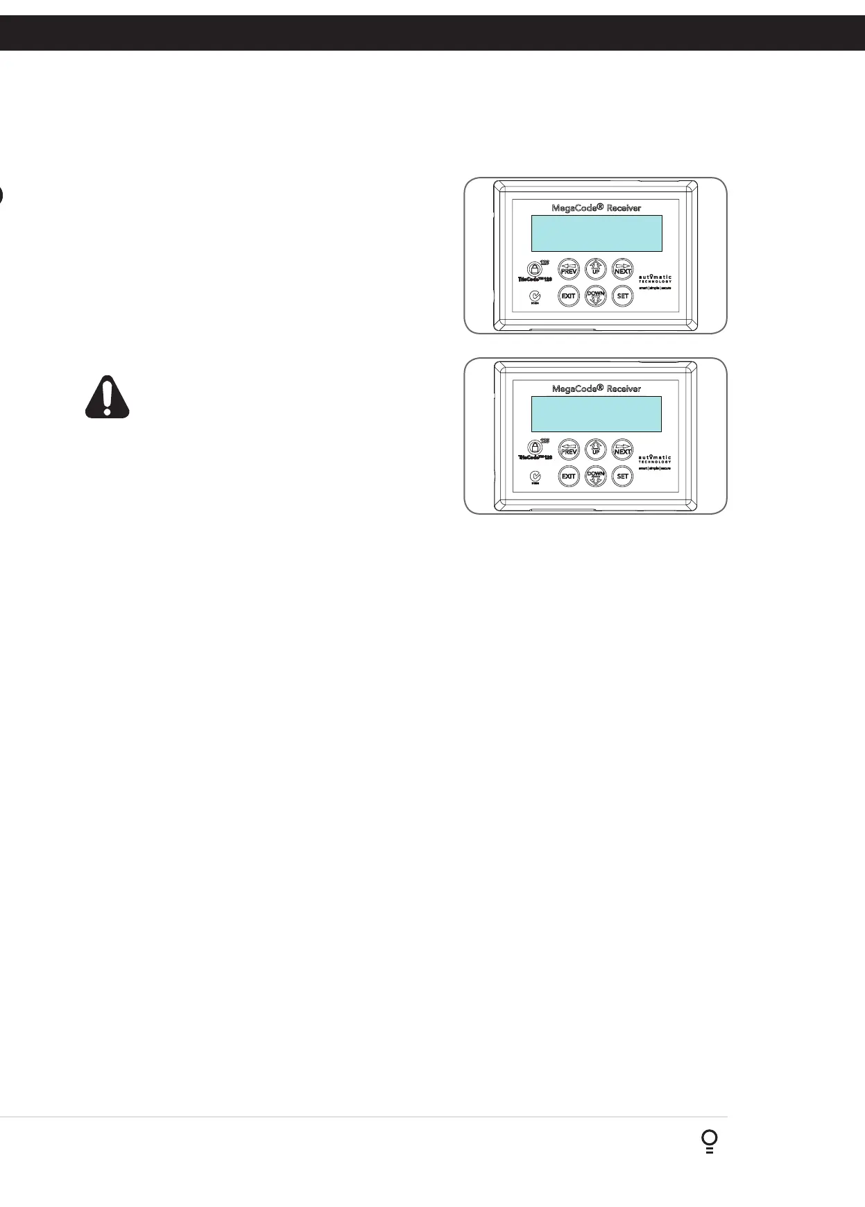
b. The receiver will go through a startup sequence displaying the
startup screen which indicates the receiver type and firmware
version (Fig. 3.1).
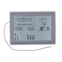
c. After a short delay the main screen will be displayed. This will
show the current time and day of the week on the top line
(Refer to section 6.2 to set the current date and time). The
bottom line will show the output status starting with Output 1
on the left through to Output 4 on the right (Fig. 3.2).
d. Make sure the time and day are set correctly.
Fig 3.1
MEGA CODE RM01
Firmware 1.10
00:00:80 STD ---
OFF OFF OFF OFF
Fig 3.2