N-29
SENSORS
CONTROLLERS
MOTION DEVICES
SOFTWARE
(J)
Temperature
Controllers
(K)
SSRs
(L)
Power
Controllers
(M)
Counters
(N)
Timers
(O)
Digital
Panel Meters
(P)
Indicators
(Q)
Converters
(R)
Digital
Display Units
(S)
Sensor
Controllers
(T)
Switching
Mode Power
Supplies
(U)
Recorders
(V)
HMIs
(W)
Panel PC
(X)
Field Network
Devices
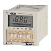
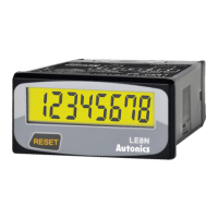
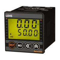
LCD Display Timer
※
Display 2
※
Display 1
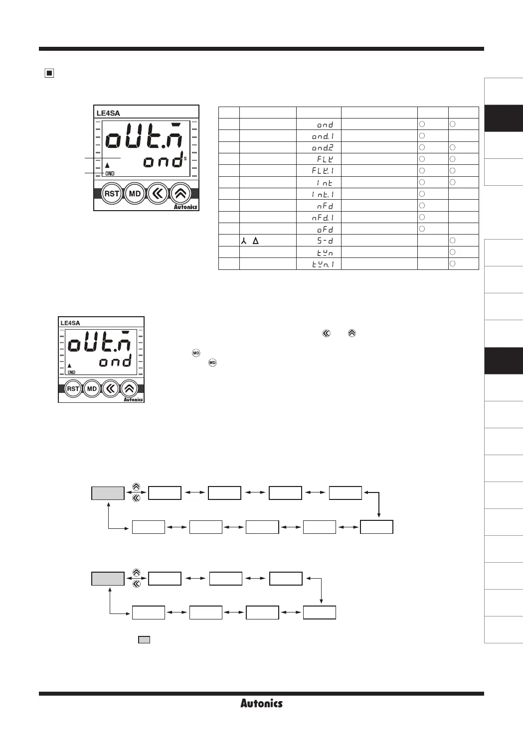
[Figure1]
Output Operation Mode
● Output operation mode
※
Output operation owchart
● LE4S/LE4SA output operation mode
NO
※
Display 1
※
Display 2 Operation mode
LE4S LE4SA
1
OND
ON Delay
2
OND
Ⅰ
ON Delay 1
-
3
OND
Ⅱ
ON Delay 2
4
FK
Flicker
5
FK
Ⅰ
Flicker 1
6
INT
Interval
7
INT
Ⅰ
Interval 1
-
8
ON OFF D
ON-OFF Delay
-
9
ON OFF D
Ⅰ
ON-OFF Delay 1
-
10
OFF D
OFF Delay
-
11
-
STAR-Delta
-
12
T
Twin
-
13
T
Ⅰ
Twin 1
-
1) In function setting mode, it enters into output operation mode as shown in the [Figure 1].
2) Select proper output operation mode using and .
(refer to Output operation owchart)
3) Press to set output operation mode and move to next mode.
4) If pressing for 3 sec in any function setting mode, it will return to Run mode.
※
The shaded parameter ( ) is factory default.
< LE4S >
< LE4SA >
OND ONd1 ONd2 FLK FLk1
INTINt1NFDNFd1OFD
ONd2 FLK FLk1
INTS-DTWN
OND
TWn1
 Loading...