1 Modbus RTU Protocol Autonics
14 © Copyright Reserved Autonics Co., Ltd.
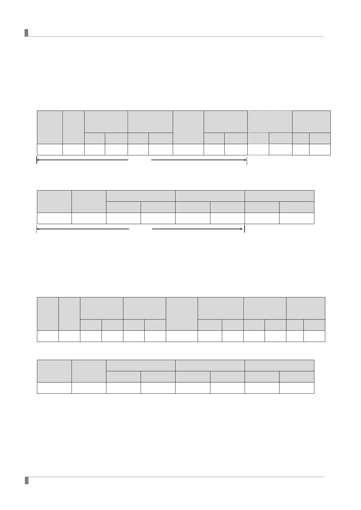
1.6 Preset Multiple Registers(Func16–10H)
Write consecutively the Binary data of Holding Registers(4X reference) in Slave device.
(1) Query(Master Side)
Slave
Address
Function
Starting
Address
No. of Register
Byte Count
Data Data
Error Check
(CRC16)
High Low High Low High Low High Low Low High
1Byte 1Byte 1Byte 1Byte 1Byte 1Byte 1Byte 1Byte 1Byte 1Byte 1Byte 1Byte 1Byte
(2) Response(Slave Side)
Slave Address Function
Starting Address No. of Register Error Check(CRC16)
High Low High Low Low High
1Byte 1Byte 1Byte 1Byte 1Byte 1Byte 1Byte 1Byte
If write “10(A H)” to both 40001(0000 H) and 40002(0001 H) of Holding Register on Slave
side(Address 17) from the Master side.
Query(Master Side)
Slave
Address
Function
Starting
Address
No. of Register
Byte Count
Data Data
Error Check
(CRC16)
High Low High Low High Low High Low Low High
11 H 10 H 00 H 00 H 00 H 02 H 04 H 00 H 0A H 00 H 0A H ## H ## H
Response(Slave Side)
Slave Address Function
Starting Address No. of Register Error Check(CRC16)
High Low High Low Low High
11 H 10 H 00 H 00 H 00 H 02 H ## H ## H
Please use the Single Register Write function rather than Multi Register Write function if
you use the slave(device) connecting with external devices such as PLC, Graphic Panel,
except in the case of download that presets minimum/maximum or basic value of the
parameter by input type in PC loader program.
 Loading...