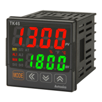
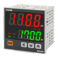
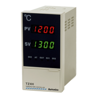
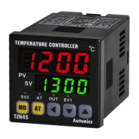
Autonics 2 Modbus Mapping Table
© Copyright Reserved Autonics Co., Ltd. 17
2 Modbus Mapping Table
2.1 Read Coils(Func01) / Write Single Coil
(Func05)
00001(0000) RUN/STOP Control Output Run/Stop 0: RUN 1: STOP
-
RUN
00002(0001) Auto-Tuning Run Auto-Tuning Run/Stop 0: OFF 0: ON
-
OFF
00003~00050 Reserved
2.2 Read Discrete Inputs(Func02)
10001(0000) ℃ Indicator Unit Indicator 0: OFF 1: ON - -
10002(0001) ℉ Indicator Unit Indicator 0: OFF 1: ON - -
10003(0002) % Indicator Unit Indicator 0: OFF 1: ON - -
10004(0003) OUT1 Indicator Control Output1 Indicator 0: OFF 1: ON - -
10005(0004) OUT2 Indicator Control Output2 Indicator 0: OFF 1: ON - -
10006(0005) AT Indicator Auto Tune Running Indicator 0: OFF 1: ON - -
10007(0006) SV1 Indicator Multi SV1 Selecting Indicator 0: OFF 1: ON - -
10008(0007) SV2 Indicator Multi SV2 Selecting Indicator 0: OFF 1: ON - -
10009(0008) SV3 Indicator Multi SV3 Selecting Indicator 0: OFF 1: ON - -
10010(0009) AL1 Indicator Alarm Output1 Indicator 0: OFF 1: ON - -
10011(000A) AL2 Indicator Alarm Output2 Indicator 0: OFF 1: ON - -
10012(000B) MAN Indicator Manual Control Indicator 0: OFF 1: ON - -
10013(000C) DI-1 input DI-1 Input Status 0: OFF 1: ON - -
10014(000D) DI-2 input DI-2 Input Status 0: OFF 1: ON - -
10015~10050 Reserved

 Loading...
