1. Fail-safe device must be installed when using the unit with machinery that may cause serious injury or substantial economic
loss. (e.g. nuclear power control, medical equipment, ships, vehicles, railways, aircraft, combustion apparatus, safety
equipment, crime/disaster prevention devices, etc.) Failure to follow this instruction may result in fire, personal injury, or
economic loss.
2. Install on a device panel to use.Failure to follow this instruction may result in electric shock.
3. Do not connect, repair, or inspect the unit while connected to a power source. Failure to follow this instruction may result in
electric shock or fire.
4. Check ‘Connections’ before wiring. Failure to follow this instruction may result in fire.
5. Do not disassemble or modify the unit. Failure to follow this instruction may result in electric shock or fire.
Caution :
1. When connecting the power input and relay output, use AWG 20 (0.50mm2 ) cable or over and tighten the terminal screw with a
tightening torque of 0.74 to 0.90Nm. When connecting the sensor input and communication cable without dedicated cable, use
AWG 28 to 16 cable and tighten the terminal screw with a tightening torque of 0.74 to 0.90Nm.Failure to follow this instruction
may result in fire or malfunction due to contact failure.
2. Use the unit within the rated specifications. Failure to follow this instruction may result in fire or product damage.
3. Use dry cloth to clean the unit, and do not use water or organic solvent. Failure to follow this instruction may result in electric
shock or fire.
4. Do not use the unit in the place where flammable/explosive/corrosive gas, humidity, direct sunlight, radiant heat, vibration,
impact, or salinity may be present. Failure to follow this instruction may result in fire or explosion.
5. Keep metal chip, dust, and wire residue from flowing into the unit. Failure to follow this instruction may result in fire or product
damage.
Ordering Information
TX 4 S 1 4 R
Control output :
R : Relay output
S : SSR drive output
C : Selectable current output or SSR drive output
Power supply :
4 : 100-240VAC 50/60Hz
Option output :
1 : Alarm output 1
2 : Alarm output 1+Alarm output 2
A : Alarm output 1+Alarm output 2+Trans. output
B : Alarm output 1+Alarm output 2+RS485 com. output
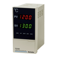
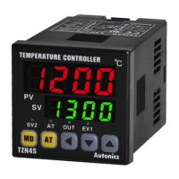
Size :
S : DIN W48×H48mm
M : DIN W72×H72mm
H : DIN W48×H96mm
L : DIN W96×H96mm
Digit :
4 : 9999(4-digit)
Item :
TX : LCD display PID temperature controller
Input Type and Range
 Loading...