25
CH100
1
10
98
54
11
67
h=12,7
32
h=5,4
11 8
53
11
10
67
2
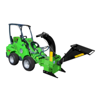
REPLACING THE BEARING
1. Open the upper chamber.
2. Remove the fastening bolts M10 (7) and the upper
bearing housings (6).
3. Mark the location of the tightening cone on the
shaft.
4. Lift the disk.
5. Bend the claw of the securing ring (3) out from the
notch on the axle nut and open the axle nut.
6. Remove the axle nut, securing ring, spacer ring (4),
bearing (5), spacer ring (9), and tightening cone
(10).
7. Install the tightening cone, spacer ring (9), and
bearing on the disk shaft. Note the thickness of
the spacer ring (9) - see Fig. 7a.
8. Install the securing ring with the claws facing
outwards and the inside claw in the groove of the
tightening cone, and install the axle nut.
9. The inner ring of the bearing should press tightly
against the tightening cone.
10. Tighten the axle nut with a hook spanner until
the bearing is tightly on the cone, or to 80 Nm.
However, the outer ring of the bearing should turn
freely. Note the location of the tightening cone on
the shaft.
11. Bend one claw of the securing ring (3) into a notch
on the axle nut.
12. Install the other half of the dust cover and end
plate on the bearing housing. Install the spacer
ring (4) on the shaft.
13. Lower the disk to the bearing housing.
14. Attach the other half of the dust cover to the
upper bearing housing; install the upper bearing
housing fastening bolts and tighten to 50 Nm.
15. Lubricate the bearing housing. An excessive
amount of grease causes overheating and impairs
lubrication.
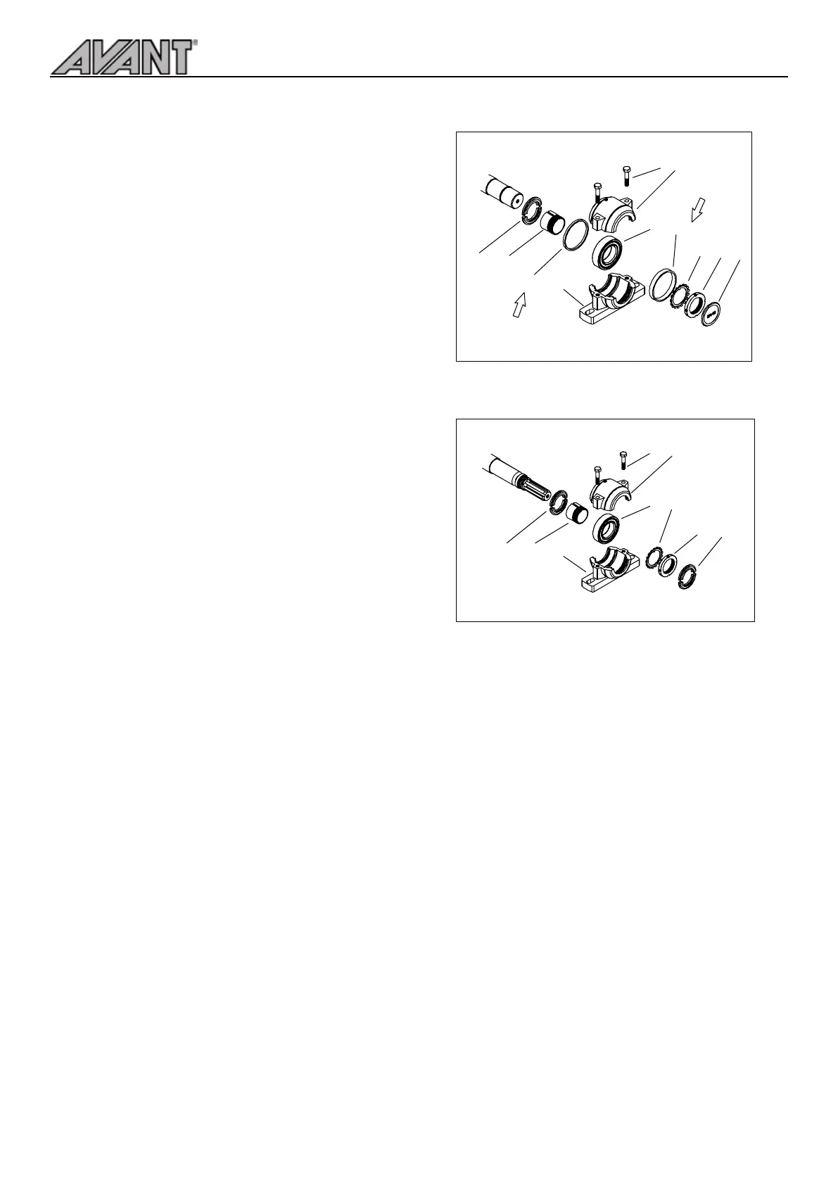
The bearings at the feeder side and splined shaft
side are dierent from each other. The bearing at
the splined shaft side, Fig. 7b., does not have spacer
rings (4 and 9) and an end plate (1). The bearing at the
splined shaft side has dust covers on both sides (11).
Fig. 7a. Bearing, feeder side
Fig. 7b. Bearing, splined shaft side