Before you begin
VSP 7000 four-post server rack-mount kit — AL7011001–E6
Tool requirements
• Phillips screwdriver to attach brackets to the switch and the switch to the rack.
• Hex wrench to assemble and attach the optional four-post rack-mount brackets.
Rack requirements
• Space of 2.8 inches (7.1 centimeters) for each switch in an E1A or 1EC standard 19–inch
(48.2–centimeter) equipment rack and T1A 23–inch (58.5–centimeter) equipment rack.
• Appropriate rack space to accommodate 1U switch height is 1.7 inches (44 millimeters).
• Four-post rack bolted to floor and braced if necessary.
• Four post-rack must be grounded to the same grounding electrode used by the power service
in the area. The ground path must be permanent and must not exceed 1 ohm of resistance
from the rack to the grounding electrode.
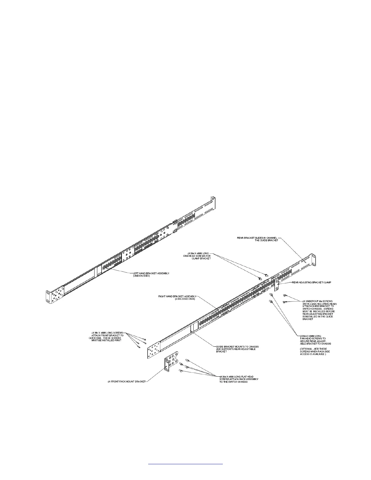
Verify that you have all the screws, brackets, and clamps to assemble and install the four-post rack
mount kit.
Figure 9: Four-post rack-mount kit assembly
Switch installation
30 Installing Avaya VSP 7000 Series August 2014
Comments? infodev@avaya.com

 Loading...