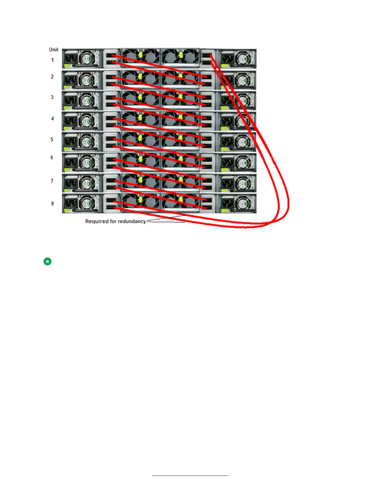
Figure 19: FI-down cable configuration
Note:
Avaya recommends that you use the FI-down configuration. Many network-management
software packages assume a down configuration.
FI-up configuration
In a FI-up configuration, the Base unit is physically located at the top of the Stack. The software
automatically numbers the physical units based on the designated Base unit (unit 1). The FI cables
connected to the FI-down ports of the Base unit terminates in the FI-up ports on the bottom unit in
the Stack. This bottom unit is designated unit 2. The Stack is wired upward though the units and the
software continues to number up though the Stack. In this configuration, the Base unit discovers the
Stack in an FI-up direction. The following figure shows a typical FI-up configuration.
Stack-mode DToR configurations
August 2014 Installing Avaya VSP 7000 Series 43
Comments? infodev@avaya.com

 Loading...