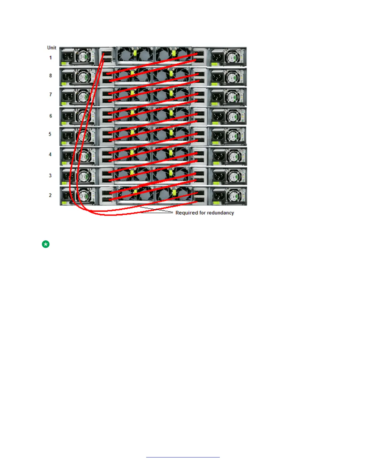
Figure 20: FI-up cable configuration
Note:
Avaya recommends that you use the FI-down configuration. Many network-management
software packages assume a down configuration.
Redundant Stack-mode configuration
The VSP 7000 Series switches support redundant Stack-mode. You can create a redundant FI
cable loop by connecting the Base unit to the unit physically at the bottom of the Stack. In a
redundant Stack-mode configuration, if a single unit fails, or if an FI cable is disconnected or
damaged, other units in the stack can remain operational without interruption.
In a redundant configuration, the software uses the FI cables to provide two paths between units. If
one path fails, the data can travel over the remaining path with half of the normal FI bandwidth. The
following is an example of how a redundant FI configuration reacts to a failed connection.
Failure example:
1. Unit 3 becomes non-operational due to a unit failure, cable disconnection, or power loss.
2. Units 2 and 4, upstream and downstream from unit 3, detects the loss of unit 3. The software
reroutes all data across the remaining path.
3. The Down LED for unit 2 and the Up LED for unit 4 turn off, indicating a connection error
occurred.
4. The Stack remains operating with half of the normal bandwidth for units 2 and 4; unit 1 has
full bandwidth.
Fabric Interconnect connectivity
44 Installing Avaya VSP 7000 Series August 2014
Comments? infodev@avaya.com

 Loading...