6
Installation
Getting Familiar with the EVC -Series
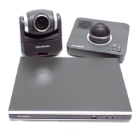
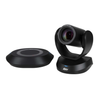
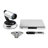
EVC includes Main System, MIC, Camera and Remote Controller.
Main System
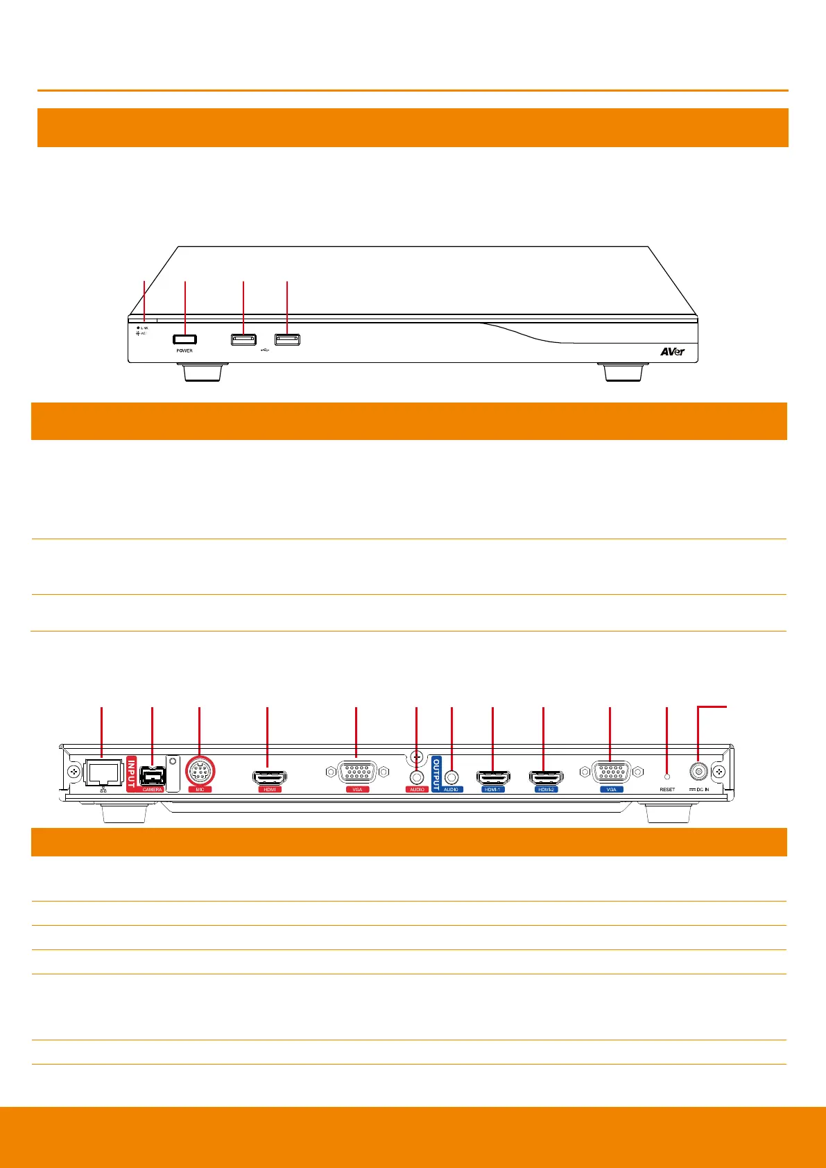
Front Panel:
Show you the status of your LAN connection.
1.
Solid Green:
LAN connection is successfully
2.
Flash Green:
Data transmission is processing through the LAN
connection.
Press this button to turn on/off main system. Red: power off; Blue: power
on
Use to connect the USB storage for system log saving and FW upgrade.
Back Panel:
(1) (2) (3) (4) (5) (6) (7) (8) (9) (10) (11)
(12)
Use the RJ-45 Ethernet cable to connect an IP-based network to the LAN
port.
Connect the camera to the main system via a camera cable.
Receive audio signal from MIC device via a mini din 8 pin MIC cable.
Through the HDMI cable connects to the PC or NB.
Connect the VGA cable to the VGA input port located on the back panel, and
connect the other end of VGA cable to a VGA input source (ex. Document
camera, Laptop or Desktop) to input video signal.
Receive audio signal from an external audio source through the audio cable.
Use to connect the main system to external speakers or amplifiers for audio
signal output.