XR Series Installation and Technical Instructions 19
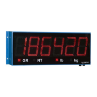
8. Ensure that the internal power cable is connected to the power supply
board. See Figure 3.1.
Figure 3.1 Power wiring
Communications Wiring All communications wiring terminates at the controller board.
Communications should be wired before applying power to the unit, if
possible.
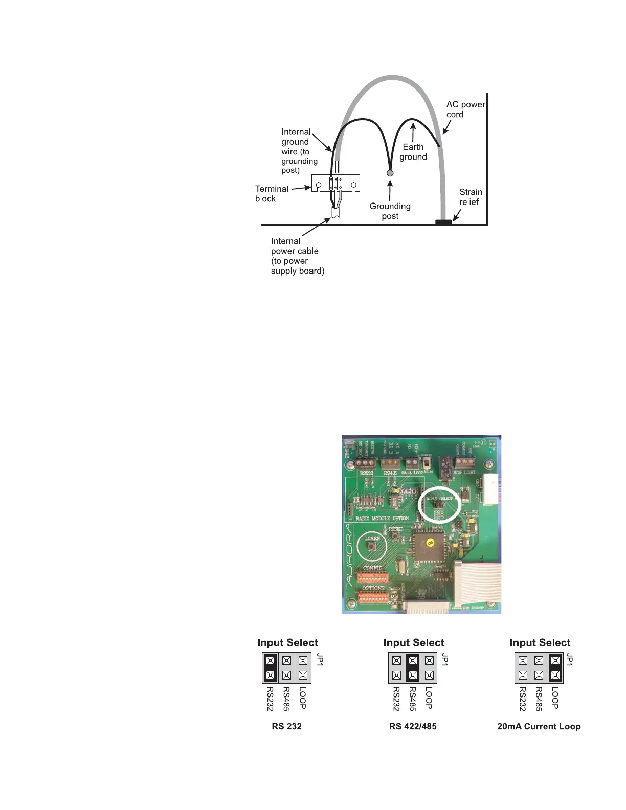
Communication Input Jumper A communications input type (RS 232, RS 422/485, or 20 mA Loop) must be
selected by placing the jumper on the appropriate pins. See photo and
illustrations in Figure 3.2. Photo shows the input select jumpers circled in a
thick white line.
Figure 3.2 Jumper positions
 Loading...