20 XR Series Installation and Technical Instructions
Wiring
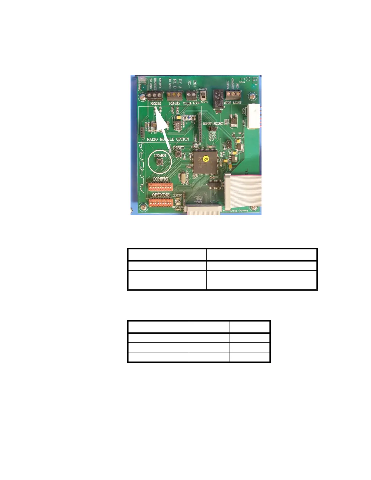
RS 232 Wiring
1. Set the Communication Input Jumper (JP 1) to RS232.
2. Terminate the indicator’s communication wires at the RS 232 terminal
(J3), shown in Figure 3.3.
Figure 3.3 RS 232 Terminal shown at arrow
See the table below for pin assignments:
RS 232 Daisy Chain
INDICATOR TO XR
TRANSMIT (TX) RECEIVE (RX)
RECEIVE (RX) NO CONNECTION
SIGNAL GROUND (GND) SIGNAL GROUND (SIG GND)
INDICATOR TO RD 1 TO RD 2
TX RX
RX TX RX
GND GND GND

 Loading...