XR Series Installation and Technical Instructions 21
RS 422 Wiring
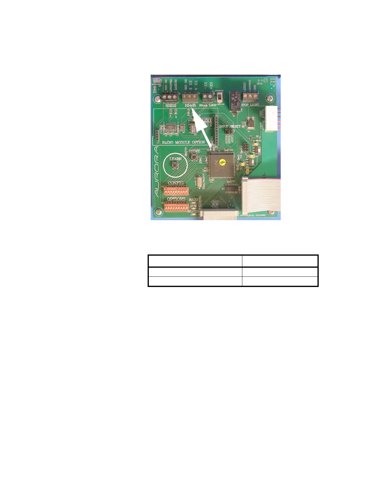
1. Set the Communication Input Jumper (JP 1) to RS485.
2. Terminate the indicator’s communication wires at the RS 485 terminal
(J4), shown in Figure 3.4.
Figure 3.4 RS 422/485 Terminal
See the table below for pin assignments:
INDICATOR TO XR
TRANSMIT A (TX A) RECEIVE A (RX A)
TRANSMIT B (TX B) RECEIVE B (RX B)
 Loading...