Chapter 4: Making Studio Connections 15
Audio Inputs
Mbox Pro provides six channels of analog in-
puts, and supports microphones, guitars, key-
boards, and other types of instruments and de-
vices.
For information about connecting specific au-
dio sources, see “Connecting a Microphone” on
page 16, and “Connecting Instruments to the
Mbox Pro” on page 19.
Mic/DI Inputs 1–2/Line Inputs 1–2
The front-panel Mic/DI inputs 1–2 provide com-
bination XLR (Mic) or a 1/4-inch (DI) jacks for
Input channels 1 and 2.
Toggle each channel’s Front/Rear input source
switch to switch between the front-panel
Mic/DI input and the 1/4-inch TRS Line Input
located on the back panel.
When the switch is in the “out” position, the
front panel Mic/DI input is active; when “in”
the rear Line Input is active.
Mic Inputs 3–4/Line Inputs 3–4
The back-panel Mic inputs 3–4 provide two ded-
icated XLR connectors for Input channels 3 and
4.
Toggle each channel’s Front/Rear input source
switch to switch between the XLR input and
1/4-inch TRS Line Input located on the back
panel.
When the switch is in the “out” position, the
Mic input is active; when “in” the Line Input is
active for that channel.
Aux Inputs 5–6
The Aux inputs 5–6 section provide dual-mono
RCA jacks or a single 1/8-inch stereo jack for
Aux input channels 5 and 6.
If the 1/8-inch jack and the RCA jacks are both
connected, the 1/8-inch jack takes precedence
over the RCA jacks.
Use these inputs to connect line-level sources
such as mixers, CD or DVD players, or MP3 play-
ers.
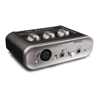
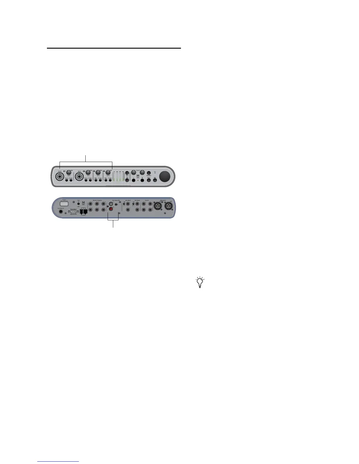
Input channels on the front/back of Mbox Pro