Do you have a question about the AVL DITEST MCS 120 and is the answer not in the manual?
Deadly high voltages are present on the HV energy store (HV battery) and on parts connected to it!
Ensure IR temperature sensor is not covered for accurate readings.
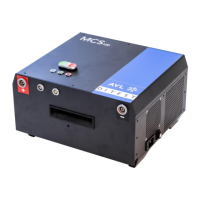
The Module Conditioning System MCS 120 is able to charge and discharge single cell modules of high voltage batteries from E-cars and hybrid cars.
The manufacturer declares that the MCS is in conformity with the following EC directives and relevant modifications.
The device delivered does not require calibration within the first 24 months after delivery; subsequent calibrations every 12 months.
It's only allowed to use the MCS 120 in that way, described in this manual.
The MCS 120 is designed for charging / discharging of single cell modules of a HV battery to a certain load level.
Illustration of the transport box with its latches and carrying handles.
Illustration of the transport box opened, showing the MCS 120 and accessories.
Illustration showing the MCS 120 unit within the opened transport box.
Illustration showing the MCS 120 unit, cell module, and adapter within the opened transport box.
Illustration showing the MCS 120, cell module, and connected cables within the opened transport box.
View of the rear of the MCS 120 unit, showing the carrying handle.
View of the right side of the MCS 120, showing air inlet grill, USB-connector, and power supply inlet.
View of the left side of the MCS 120, showing specification plate and air inlet grill.
Illustration of the front of the MCS 120, detailing connectors, LEDs, and buttons.
Overview of various cable sets used with the MCS 120, including USB and connection cables.
Description and image of the USB cable connecting the MCS to a PC.
Description and image of the plus and minus cables with knurled screw.
Description and image of the cable for connecting analog cell voltage module taps.
Description and image of the cable to connect digital cell voltage modules via CAN bus.
Description and image of the cable used to connect modules with TPL communication.
Instructions for installing the DSS Software, noting prerequisites like admin rights and specific document references.
Note regarding firmware updates, referencing specific documentation for the process.
Instructions for hardware setup, including temperature compensation and ventilation requirements.
Steps to start the MCS 120, including launching the DSS Manager and selecting the Module Balancer.
Procedure for performing a safety test using the DSS Manager, involving connecting cables and closing covers.
Steps to perform a self-test on the MCS 120 using the DSS Manager, displaying test results.
Procedure to view device data, including software version, serial number, and calibration date.
Function to manage result protocols, allowing users to select, view, print, delete, export, or archive reports.
Instructions on how to change the default location for storing result protocols for backup and transmission.
Function to manage operator names for use in charge/discharge operations, allowing adding, editing, and selecting operators.
Procedure for switching off the MCS 120, which involves turning off power modules and disconnecting the power cable.
Warning about electrical shock and restriction on opening the device for maintenance.
Instructions for performing a regular optical check of the MCS 120, USB cable, and test adapters for damage and dirt.
Procedure for cleaning the MCS 120 housing using a dry cloth, with safety precautions before cleaning.
List of parts included in the standard delivery of the MCS 120, along with their ID numbers.
List of available spare parts for the MCS 120, including cable sets and adapters.
Details on AC power grid requirements, charging/discharging power, cell monitoring, external interface, and ambient conditions.
Information on the proper disposal of the AVL DITEST product, emphasizing compliance with local legal requirements.
| Brand | AVL DITEST |
|---|---|
| Model | MCS 120 |
| Category | Control Unit |
| Language | English |