CONNECTION AND SETUP
5
2.2 Camera Connection
Install the camera on the wall or ceiling based on your installation environment and camera type. For installation
details, please refer to the user manual of your camera.
2.2.1 Normal / DCCS Camera
1) Connecting to DVR video input
Connect the camera video output to the DVR video input port with a coaxial cable or RCA line with a BNC
connector.
Note: For connecting a DCCS-type camera, make sure your DVR model supports DCCS, the camera is
connected to the 1
st
video channel (CH1), and the distance between the camera and DVR needs
to be within 200 meters by using a 3C2V coaxial cable (112 braids) for DCCS control to take
effects. For more details, please refer to “2.8 Examining DCCS Signal Transmission” at page 9.
2) Connecting to DVR audio input (Optional)
Connect the camera audio output to the DVR audio input port with a coaxial cable or RCA cable with BNC
connectors.
3) Connecting to power
Connect the camera with indicated power supply and make sure it’s power-supplied.
2.2.2 PTZ Camera
The following description is taking our brand’s PTZ camera as an example.
Note: The RS485 wiring is not needed when your DVR and PTZ camera both support DCCS, and the
video channel your PTZ camera connects is CH1. If yes, please go to STEP 5 directly for PTZ
camera setting.
For detailed PIN / port connection, please refer to “APPENDIX 2 PIN CONFIGURATION” at page 64. For detailed
PTZ camera control and operation, please refer to its own user manual.
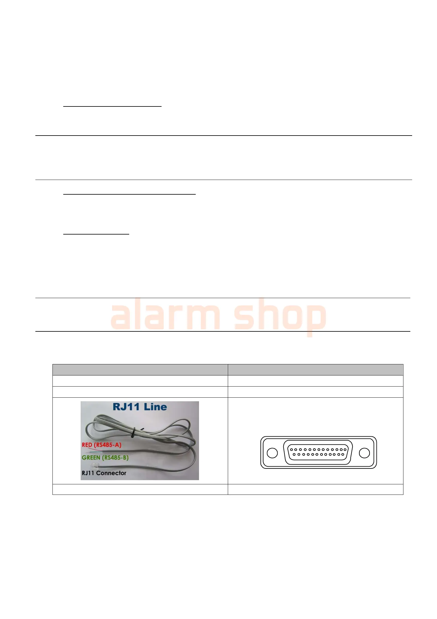
RJ11 cable 25 PIN D-Sub Connector
RS485-A: Red wire RS485-A: PIN 12
RS485-B: Green wire RS485-B: PIN 24
1
1516171819202122232425 14
2345678910111213
Solder Side o
25-pin D-Sub connector
RS485 -A: PIN12 / RS485-B: PIN2 4
The RJ11 cable is not supplied in the sales package. The D-Sub connector is not supplied with the DVR package.
STEP 1: Get a RJ11 cable with the proper length to your connection.
Different RJ11 connector may have different wire layout, so the connection might be different. If you
cannot control the DVR after connection, please reverse the RJ11 cable connection with the DVR.
STEP 2: Remove one end of the insulating coating of the RJ11 cable.
Remove one end of the insulating coating of the RJ11 cable to find the RS485-A and the RS485-B wires,
and remove the insulating coating to reveal the naked wires for further connection.