Home
Avtron
Control Unit
ADDvantage-32
Avtron ADDvantage-32 User Manual
5
of 1
of 1 rating
290 pages
Give review
Manual
Specs
To Next Page
To Next Page
To Previous Page
To Previous Page
Loading...
Control Block Description
ADDvantage-32
4-31
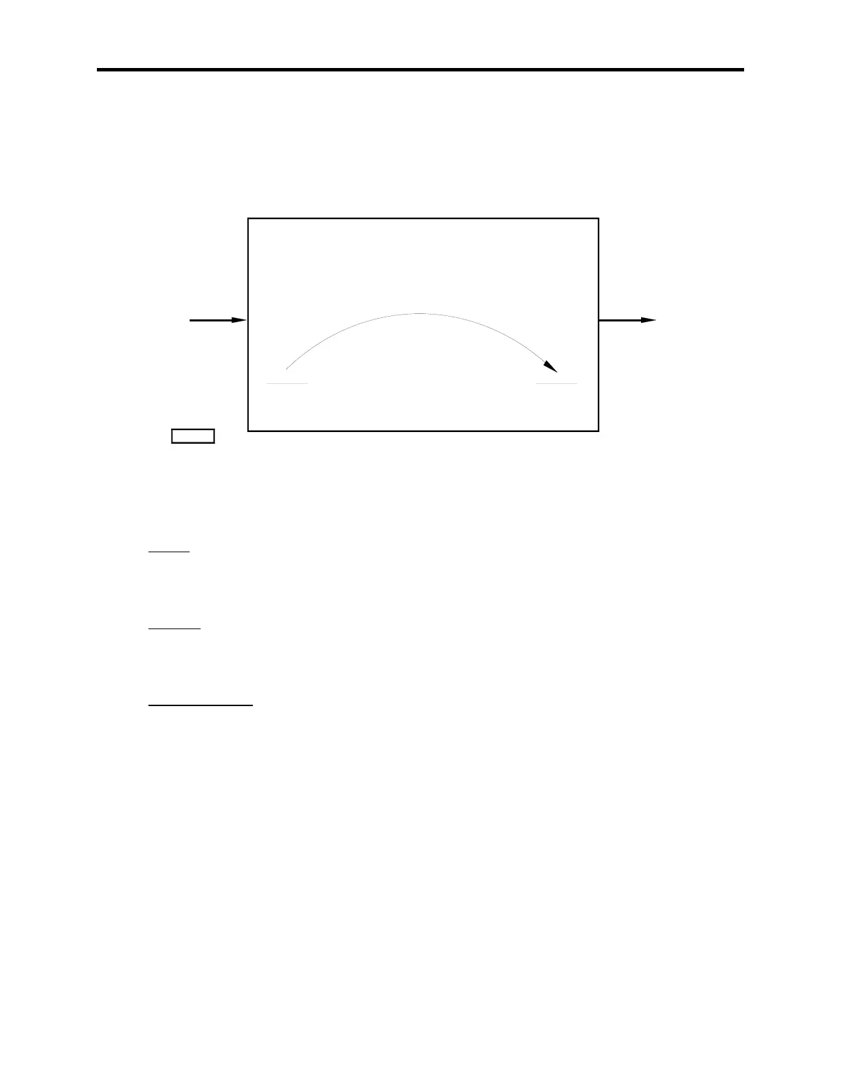
4.22 COPY
The Copy block takes the analog value at the input and copies the value to the output.
INP
OU
T
COPYD101
COPY BLOCK
FIGURE 4-22. COPY BLOCK
1. Inputs
INP:
Analog
2. Outputs
OUT:
Analog
3. Implementation
OUT = INP
92
94
Table of Contents
Table of Contents
5
Supplemental Data
5
Safety Summary
7
Warning
9
System Safety Considerations
11
ADD-32 DOK Fault Contact
11
Advanced Control Module
13
Introduction and General Information
13
Description
13
Standard Features
13
Hardware and Equipment Features
14
Microprocessor Board
15
Original Microprocessor Board
15
Low Memory Microprocessor Board
16
High Memory Microprocessor Board
16
System PC Board
17
MINI System Board
18
Maxi System Board
18
FAX-32 Board
19
Power Supply Board
20
Software Features
21
Software Format
21
Identification of Part Numbers
22
Hardware Part Number
22
Software Part Number
22
Hardware Part Number Breakdown
23
Model Type
23
System Boards
23
Microprocessor Boards
23
Software Part Number Breakdown
24
Specifications
25
Digital Input Ratings
25
Keyboard and Parameter Functions
29
Key Functions
30
Keypad and Display
30
Menus and Submenus
31
Keypad Flowchart
32
Parameter Definition and Groupings
33
Parameter Groups
33
Parameter Layout
34
Parameter Organization
34
Numeric Type Parameter Format
36
Numeric Format
36
Editing a Numeric Parameter
37
Configuration Type Parameter Format
38
Configuration Format
38
Editing a Configuration Parameter
39
Parameter Description Chart
40
Core Software Operation
45
Dedicated Inputs
45
Emergency Stop
45
Dedicated Outputs
46
Emergency Stop Reset
46
Drive O.K.
46
RUN Command
46
Logic Sequence
48
Drive Sequence Rung Descriptions
48
Run, Thread and Jog Inputs
51
Analog Inputs
52
Analog Output Functions
53
Frequency Inputs
54
Averaging Method
54
Direct Count Method
55
Counters
56
Hardware Configuration and Diagnostic Parameters
57
User Fault Inputs
58
Motor Thermal Settings
58
Motor Stall Protection
59
Control Block Description
61
Table of Contents
61
2 And
63
2 Or
65
4 Analog Select
66
5 And
68
5 Summer
69
Five Summer Block
69
8 Bit Invert
71
8 Bit Invert Block
71
Absolute Value (Abs)
72
Absolute Value Block
72
Analog Invert
73
Analog Invert Block
73
Analog Select
74
Analog Select Block
74
Analog Switch
75
Analog Switch Block
75
Asm Auto Sheet Marker
76
Asm Auto Sheet Marker Block
76
Balance
78
Balance Block
78
Bit Convert
80
Bit Convert Block
80
Bit Convert Block out Values
81
Bit Invert
82
Bit Invert Block
82
Bit Select
83
Bit Select Block
83
Bumpless Switch
84
Bumpless Switch Block
84
Cds Counts During Stop
86
Cds Counts During Stop Block
86
Clamping
88
Clamping Block
88
Com Loss
90
Com Wd
91
Comparator
92
Comparator Block
92
Copy
93
Copy Block
93
Current Limit
94
Non-Tapered Current Limits
95
Tapered Current Limits
96
Block Positive Bridge
96
Block Negative Bridge
96
Current Limit Block Diagram
97
Deadband
98
Deadband Block
98
Demux
99
Demux Block
99
Density
100
Density Block
100
Derivative Gain (D/Dt)
102
Diff Trip
103
Diff Trip Block
103
Digital in
105
Digital or
107
Digital or Block
107
Divide
108
Divide Block
108
Droop
109
Droop Block
109
Eip Tout
110
Eip Tout Block
110
Error
112
Frequency out
113
Frequency out Block
113
Gain
114
Hi/Low Comparator
115
Hi/Lo Comparator Block
115
Iit
117
Iit Block
118
Latch
119
Latch Block
119
Lead/Lag
121
Lead Lag Block
121
Least Win
123
Lowpass Filter
124
Lowpass Filter Block
124
Most Win
125
Mov8
126
Mov8 Block
126
Multiply
128
Multiply Block
128
Notch Filter
129
Notch Filter Block
129
Off Timer
131
Off Timer Block
131
On Timer
132
One Shot
133
One Shot Block
133
Peak Detect
134
Peak Detect Block
134
Percent Difference
135
Percent Difference Block
135
PERCENT MULTIPLY (Per Mult)
136
Proportional and Integral Control (Pi)
137
Proportional and Integral Control with Cascaded Hold Bits (Pi2)
140
Quad Ltch
143
Quad Ltch Block
143
Ramp
144
Ramp Block
144
Rate Change
146
Rate Change Block
146
Ratio
147
Ratio Block
147
Non-Retentive Block
148
Retentive Block
148
Recipe
149
Recipe Block
150
Resolver 1
151
Resolver 1 Block
151
Rmp2
153
Rmp2 Block
153
Ramp Change Block
154
Rate of Change Limit Block
155
Additional Control I/O
158
Rramp3
161
Internal Control Blocks
162
Sbxdia
164
Sbxdia4
166
Sbxdia4 Block
166
Sds Sheets During Stop
169
Sds Sheets During Stop Block
169
Setpoint
171
Setpoint Block
171
Snapavg
174
Snapavg Block
175
Splicer
176
Splicer Block
176
Summing Junction, Selectable 3 Input
178
Summing Block
178
Table Block
179
Tach Select and Tach Select-W
181
Timer
185
Timer Block
185
Type 2 Dia
187
Type 3 Dia
189
Type 3 Dia Block
189
Unity Scale
191
Unity Scale Block
191
Uv Protect
192
Uv Protect Block
192
Winder Wk/D
194
Window Compare
196
Window Compare Block
196
Signal Analyzer
199
Data Collection
199
Trigger
200
Sample Rate
201
Preview
201
Arming
202
Enable
202
Reset
203
Done Bit
203
Analog out
203
Automatic Recording of Signal Analyzer
205
Manual Recording of Signal Analyzer
206
Preparation for Use
207
Unpacking
207
Mechanical Installation and Specifications
207
Storage and Installation Specifications
208
Mounting Specifications
208
Location
208
Electrical Connections
209
Location of Other Equipment
209
Block Diagram, Power Connections
210
Block Diagram, Mini System Board
211
Mini System Board Interconnections
214
Maxi System Board Interconnections
215
FAX-32 Board Interconnections
216
Electrical Installation
217
Wiring Practices and Notes
217
Installation Checkout
219
Power up and Start up
219
Pulse Generator Installation
219
ESD Precautionary Guidelines
221
Maintenance and Troubleshooting
223
Maintenance Requirements
223
Periodic Maintenance
223
General Diagnostic Features
224
Initial Power up Check
225
LED Definitions
226
Powerup Messages
227
Faults and Warnings
228
Types of Warnings and Faults
228
Hardcoded Faults and Warnings
229
Fault Descriptions
230
Ftype Failure Type Procedures
232
Typical Display
232
Board Replacement
233
Replacing Microprocessor Board
233
Replacing System Board
233
Replacing System and Microprocessor Boards
234
Replacing Power Supply Board
235
Fuse Replacement
236
Overview
237
ESBX Ethernet Board
238
Avtron ESBX Module
239
Hardware Requirements
242
Software Requirements
243
Drive ID/IP Address
243
Drive Ethernet Configuration
244
Drive Calibrate Menu
245
Drive IP Address
245
Drive Subnet Mask
246
Gateway Address
246
Machine Number
247
Web Password
247
Drive Configure Menu
247
Y Parameters
247
Downloading Firmware to ESBX Ethernet Boards
248
Ethernet Switches
251
Plc's
252
Addapt 2000
253
Ethernet Communication Troubleshooting
254
Drive Ethernet Diagnostics Definitions
260
PPR Send Fail
261
PPR Xmit Fail
261
PPR no Reply
261
QRY Frames
261
Ethernet Communications Protocols
262
Transmission Concepts
262
User Datagram Protocol
262
Transmission Control Protocol
263
Demultiplexing Based on Ports
263
Tcp
264
Network Addressing Concepts
265
Class-Based IP Addresses
265
Sub Net Classes
265
Broadcast Addressing
266
Multicast Addressing
266
Interconnect Issues and Notes
267
Avtron Supported Protocols
267
ADD32-EGD Interface
268
Analog Table
268
Digital Table
268
Schneider Electric Modbus
269
Ethernet Communications Using Allen-Bradley
270
System Data Structures
271
Data Tables
271
Data Table Structures
271
Data Files
273
File Number Description
274
File 9 - Analog I/O
274
File 10 - Adt Labels
275
File 11 - Adt Units
275
File 12 - Default Adt Units
275
File 13 - Cal Table Units
275
File 15 - Cal Table Lolim
276
File 16 - Cal Table Hilim
276
File 17 - Cal Table
276
File 18 - Control Cal Labels
276
File 19 - Control Cal Hi Lims
277
Control Cal lo Lims
277
File 21 - Control Cal Defaults
277
File 22 - Control Config Legals
277
File 28 - Dig Io
278
File 29 - Ddt Labels
278
File 30 - Drive Cal Labels
279
File 31 -Drive Cal Units
279
File 32 - Drive Cal Hi Lims
279
File 33 - Drive Cal lo Lims
279
File 37 - Drive Config
280
File 38 - Drive Cal
280
File 39 - Select List Labels
280
File 40 - Checksum Area
280
File 41 - Cal Version
281
File 42 - Software Part Number and Version Number
281
File 43 - Time Array
281
File 44 - Analyzer Cal Labels
281
File 45 - Analyzer Cal Hi Lims
282
File 46 - Analyzer Cal lo Lims
282
File 47 - Analyzer Cal Defaults
282
File 48 - Analyzer Cal
283
File 49 - Analyzer Config Label
283
File 50 - Analyzer Config Legals
283
File 51 - Analyzer Config
283
Files 52 through 55 - Diagnostic Status Tables
284
Files 56 through 59 - Diagnostic Trace Data Tables
284
File 60 - Fault Table
285
File 61 through 62 Keyboard/Display Mode Tables
286
MSG Configuration for Autoscan Write
288
Autoscan Read
289
MSG Configuration for Autoscan Read
290
File 63 through 64 _Misc. Status Files
290
File 65 through 68 Diagnostic Trace Control Files
290
5
Based on 1 rating
Ask a question
Give review
Questions and Answers:
Need help?
Do you have a question about the Avtron ADDvantage-32 and is the answer not in the manual?
Ask a question
Avtron ADDvantage-32 Specifications
General
Manufacturer
Avtron
Type
Control Unit
Model
ADDvantage-32
Number of Channels
32
Humidity
5% to 95% non-condensing
Communication Interface
RS-485
 Loading...