AXELL OPTICAL MASTER UNIT MARK II
PRODUCT DESCRIPTION AND USER’S MANUAL
© Axell Wireless Ltd Doc PN 00018UM Rev. 1.9 3
1.2 Architecture
OMU II comprises of a chassis in which various modules are installed and whose rear panel varies
(model dependent) to support one RF sector, two RF sectors or up to eight RF sectors (the latter
requires the use of a POI unit).
OMU II main function is to perform the RF to optic conversion from the RF source and route the
optic signal over the optical fibres towards fibre-fed Axell remotes. Two main types of remotes are
supported: high-power and low-power. Each optic conversion module provides power to a single
high-power remote, where up to 8 optic conversion modules are supported.
To support low-powered fibre-fed remotes, an optic splitter module is used to split the optical signal
from one converter into four, feeding four low-powered fibre-fed remote units. Thus, various
combinations of supported remote units can be achieved, within the given limitations. The valid
combination of both high-power and low-power remotes per OMU II is detailed in section
1.5.
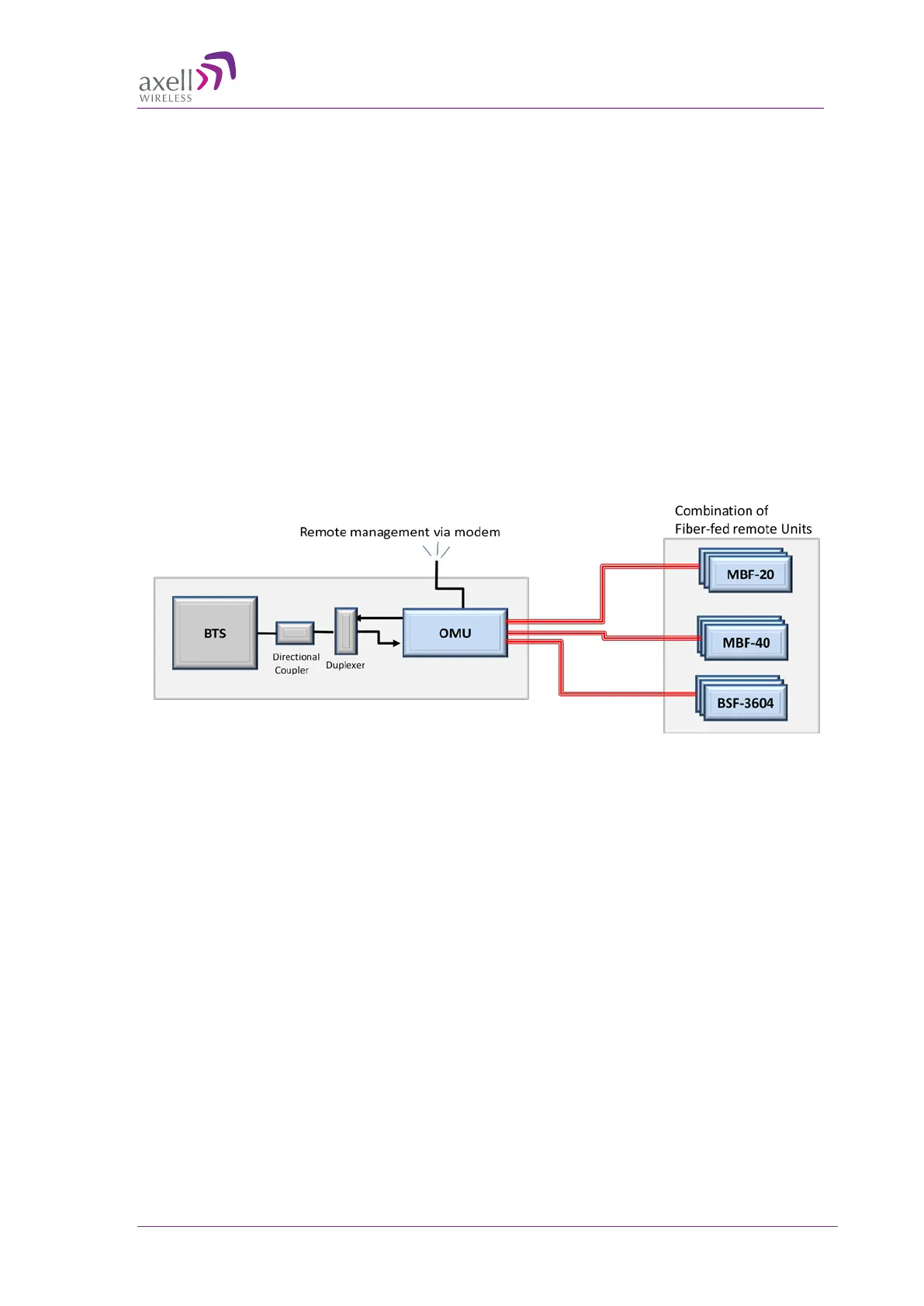
Below is a general example of an OMU II configuration fed by a single sector (BTS) and a
combination of high power (e.g. MBF-40, BSF-3604) and low power (MBF-20) remote fibre-fed
units.
Figure 1-1. Overview of OMU II Architecture
 Loading...