AXELL OPTICAL MASTER UNIT MARK II
PRODUCT DESCRIPTION AND USER’S MANUAL
8 Doc PN 00018UM Rev. 1.9 © Axell Wireless Ltd
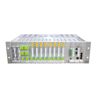
1.6.2 Optic Splitter
Location: see Figure
1-6.
Splits an optic signal from the connected WDM fibre-optic converter to four
F/O signals used to feed four MBF-20 units
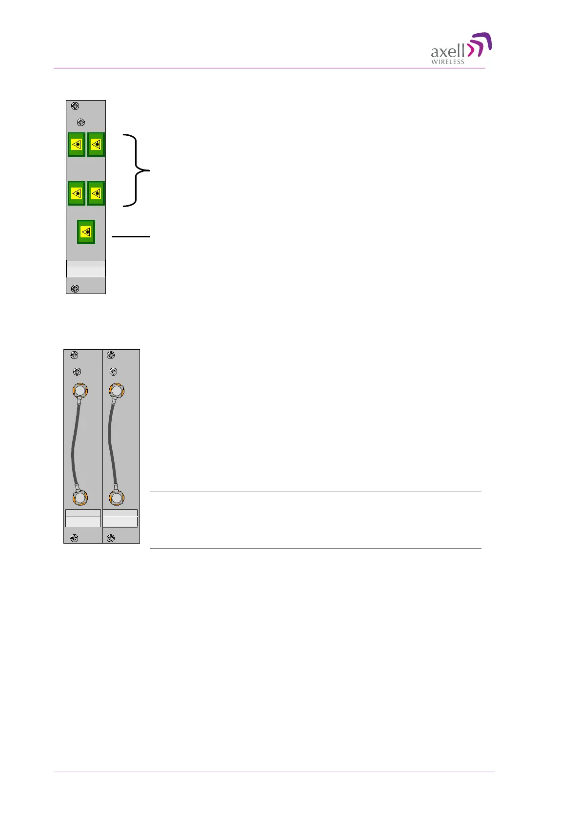
1.6.3 RF Splitter and RF Combiner Modules
Location: see Figure 1-6.
Each pair of modules supports interface to one RF service. Depending on
whether the ports are shorted, the service(s) can be connected from the front
(or rear of the chassis).
• Combine and distribute the RF signals between the OMU’s RF port and
up to six Fibre Optic modules.
• Allows for Front Panel connection to RF source (e.g BTS).
• Contains attenuators used to set the master signal levels in the downlink
and uplink.
Note: By default, the module ports are interconnected (UL In to RF out) to
allow RF connections at the rear of the unit. However, these may be
disconnected to allow RF connections at the front of the unit for tests or
troubleshooting.
Converter port
MBF-20 remotes
 Loading...