AXELL OPTICAL MASTER UNIT MARK II
PRODUCT DESCRIPTION AND USER’S MANUAL
© Axell Wireless Ltd Doc PN 00018UM Rev. 1.9 7
1.6 OMU II Front Panel Modules
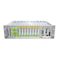
OMU II chassis is designed for a 19” rack. It houses a number of different modules where the types
of modules must be inserted in specific slots. For reference, the slots in the image below are
numbered from left to right. Each of the modules is described in detail in the following sections.
The OMU II has 12 connector slots configured, where specific types of modules must be inserted in
the relevant slots.
Figure 1-6. Axell OMU Front Panel Interfaces
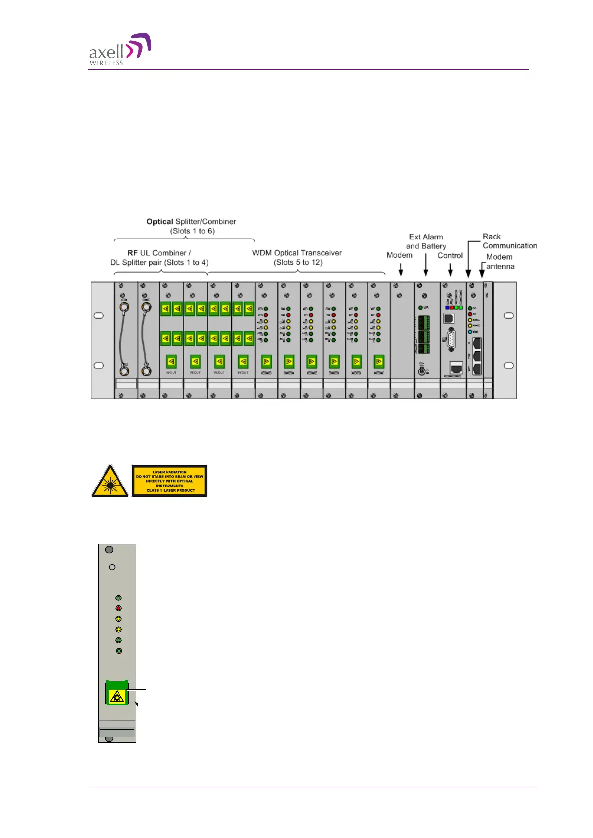
1.6.1 WDM Fibre Optic Converter
Caution: Class 1 Laser
Caution!!! Un-terminated optical receptacles may emit laser radiation.
Do not stare into beam or view with optical instruments.
Location: see Figure
1-6.
Provides WDM (single fibre) RF to optical signal conversion.
• Interfaces via the fibre (SC/APC port) to one of the following:
o One high-power fibre-fed remote or
o To an Optic Splitter module for feeding four low power
fibre-fed remotes.
• Six LED indicators: power status, error, (2) data communication
and (2) optic signals. See section 6.2.1 for more details.
ERR
PWR
UL
DATA
DL
DATA
OPTO
Rx
OPTO
Tx
SC/APC
Optic port
 Loading...