AXELL OPTICAL MASTER UNIT MARK II
PRODUCT DESCRIPTION AND USER’S MANUAL
© Axell Wireless Ltd Doc PN 00018UM Rev. 1.9 5
1.4 Point-of-Interface (POI)
The POI unit is used with specific OMU II models whose rear panel is designed for interface with the
POI. This type of installation provides user customizable configurations of up to eight sectors that
can be routed to user selectable optical conversion units.
The POI front panel provides the interfaces for up to eight RF sectors, whereas the rear panel allows
the user to associate each sector to any of the OMU II optical conversion modules.
1.5 Supported Combinations of High-powered and
Low-powered Units
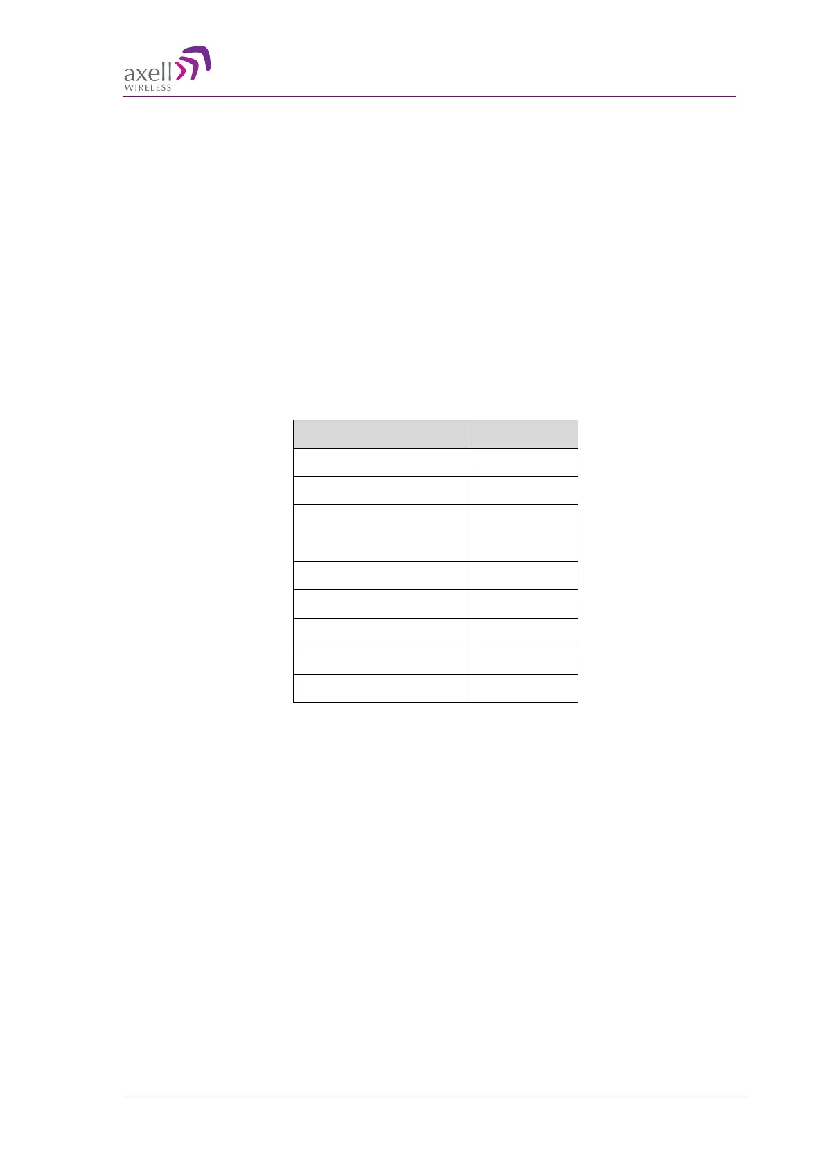
The following table demonstrates the available remote combination in a single OMU system. Note
that the extreme options are for only high-power remotes - up to eight are supported; only low-power
remotes - up to 24 are supported. In addition, the available combinations of both types of units.
# of MBF-40 / BSF-3604 # of MBF-20
8 0
7 4
6 8
5 12
4 16
3 16
2 20
1 20
0 24
Figure 1-3. Remote Combination Table
 Loading...