AXELL OPTICAL MASTER UNIT MARK II
PRODUCT DESCRIPTION AND USER’S MANUAL
© Axell Wireless Ltd Doc PN 00018UM Rev. 1.9 9
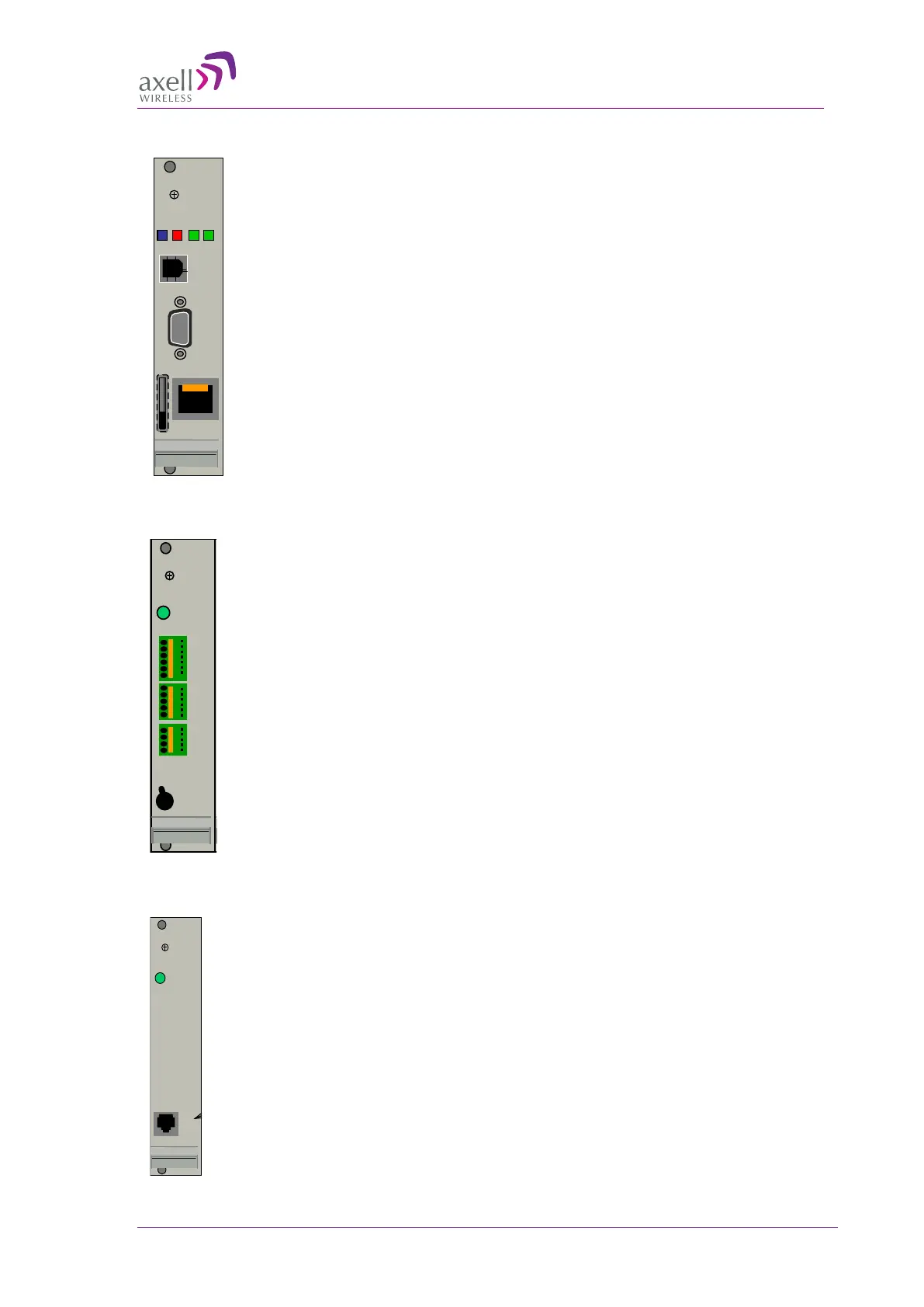
1.6.4 Control Module
Location: see Figure
1-6.
Provides control and management connections. These include local Ethernet
(and USB) management Web management and a modem.
Manages and controls the OMU and transmits alarms to the control centre.
• Includes a Real Time Clock (RTC) with a dedicated backup battery.
• Status LEDS:
o Modem Status
o Modem Power
o Status
o Login
1.6.5 External Alarm and Battery Module
Location: see Figure
1-6.
• Supports connections for four dry-contact external alarms and an alarm
relay (output alarm).
• ON/Off switch – can switch On/Off rechargeable battery pack. When
on, allows the modem to transmit an alarm in case input power loss is
detected. Switch for ON/OFF.
• LED - Power
1.6.6 Modem Unit
Location: see Figure
1-6.
• Optional – if a modem is not available on the Control unit. For
example, PSTN modems or wireless modems with a form factor that
prevents it from being integrated with the Control Module.
• The access to a PSTN modem is via an RJ11 connector on the front of
the module.
Modem Status
Modem Power
Status
Login
.
.
.
.
.
.
.
.
.
.
.
.
.
.
.
.
.
.
LMT Port
Ethernet
 Loading...