UMAX140900. Ethernet to CAN Converter. Version 5 Page: 6-35
A powerful ARM Cortex-M4 microcontroller runs IP protocol stack and all Ethernet to CAN
conversion logic.
2.2 LED Indicators
There are three LED indicators on the front panel of the converter. A bi-color “Power” indicator
shows whether the unit is powered. It turns red when there is an error on the CAN power
output.
The two Ethernet LED indicators are hardwired to the PHY chip and show the transmission
speed “Ethernet 10/100” and the link/activity status “Ethernet Link/Act”, see Table 1:
Table 1. Converter LED Indicators
The converter is not powered.
The converter is powered. CAN Power
Output is in normal condition.
CAN Power Output is in a fault condition.
Ethernet speed is 100 Mbit/s
Ethernet speed is 10 Mbit/s
Ethernet link is up and active
2.3 Firmware Organization
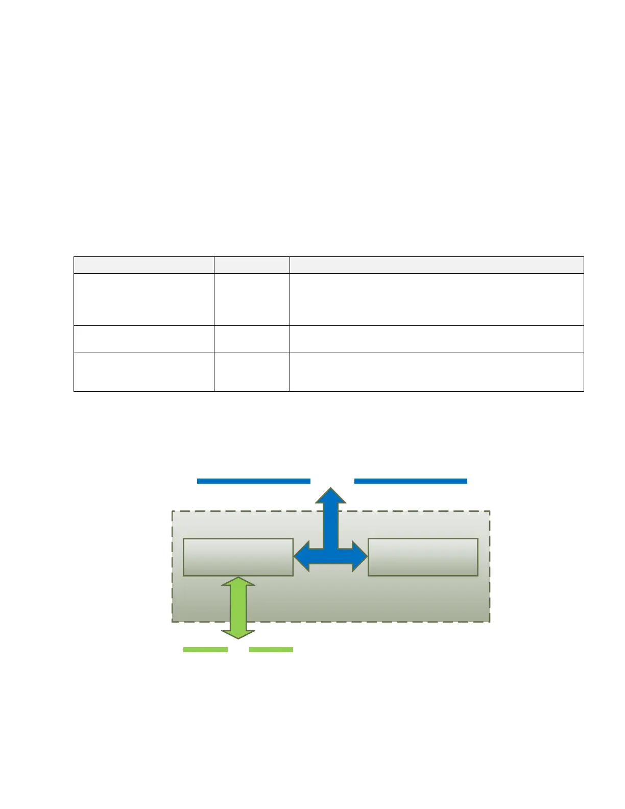
The Ethernet to CAN Converter firmware contains two independent parts: the Communication
Device and the Web Server, see Figure 2:
Ethernet
CAN
Communication Device
Web Server
IP network
Figure 2. Converter Firmware Architecture
The Communication Device is responsible for the protocol conversion between CAN and
Ethernet networks and the Web Server provides the converter user interface.
Both the Communication Device and the Web Server use the same IP network interface. The
IP address resolution is provided by the ARP protocol.