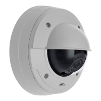
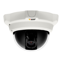
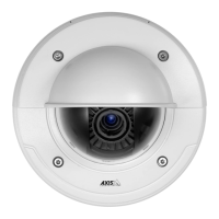
AXISP3364-LVNetworkCamera
NetworkLEDIndication
Green
Steadyforconnectiontoa100Mbit/snetwork.Flashesfor
networkactivity.
Amber
Steadyforconnectiontoa10Mbit/snetwork.Flashesfor
networkactivity.
UnlitNonetworkconnection.
PowerLEDIndication
Green
Normaloperation.
Amber
Flashesgreen/amberduringrmwareupgrade.
ConnectorsandButtons
Forspecicationsandoperatingconditions,seepage13.
NetworkConnector
RJ45EthernetconnectorwithPoweroverEthernet(PoE).
NO NO
NO
TICE TICE
TICE
Theproductshallbeconnectedusingashieldednetworkcable(STP).Allcablesconnecting
theproducttothenetworkshallbeintendedfortheirspecicuse.Makesurethatthe
networkdevicesareinstalledinaccordancewiththemanufacturer’sinstructions.For
informationaboutregulatoryrequirements,seeElectromagneticCompatibility(EMC)on
page2.
I/OConnector
Usewithexternaldevicesincombinationwith,forexample,tamperingalarms,motiondetection,
eventtriggering,timelapserecordingandalarmnotications.Inadditiontothe0VDCreference
pointandpower(DCoutput),theI/Oconnectorprovidestheinterfaceto:
•Digitaloutput–ForconnectingexternaldevicessuchasrelaysandLEDs.Connected
devicescanbeactivatedbytheVAPIX®ApplicationProgrammingInterface,output
buttonsontheLiveViewpageorbyanActionRule.Theoutputwillshowasactive
(shownunderSystemOptions>Ports&Devices)ifthealarmdeviceisactivated.
•Digitalinput–Analarminputforconnectingdevicesthatcantogglebetweenanopen
andclosedcircuit,forexample:PIRs,door/windowcontacts,glassbreakdetectors,
etc.Whenasignalisreceivedthestatechangesandtheinputbecomesactive(shown
underSystemOptions>Ports&Devices).
12