Page 14 AXIS Q7404 Installation Guide
Unit connectors
Network connector - RJ-45 Ethernet connector. Shielded Cat-5e or Cat-6 cables are
recommended.
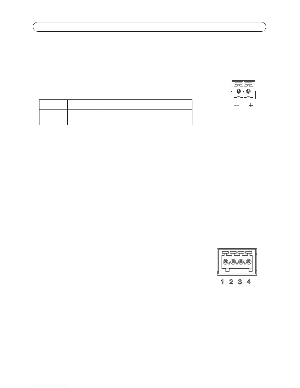
Power connector - Power input. Use the supplied power adapter or an external
power supply 8-20V DC, max. 16.1W.
Video inputs - AXIS Q7404 supports four video sources (VIDEO 1 - VIDEO 4). Each video input is
terminated using a coax/BNC connector. Use a 75 ohm coaxial video cable; recommended
maximum length is 250 meters (800 feet).
Note: If the video source is to be connected in parallel with other equipment using a BNC T adaptor, disable
the input termination by setting the 75 ohm termination switch to OFF. Failure to do so may cause
reduced image quality.
Audio connectors - AXIS Q7404 has two audio connectors connected to video channel 1:
• Audio in – 3.5 mm input for a mono microphone, or a line-in mono signal (left channel
is used from a stereo signal).
• Audio out – 3.5 mm output (line level) that can be connected to a public address (PA)
system or an active speaker with a built-in amplifier. A pair of headphones can also be
attached. A stereo connector must be used for the audio out.
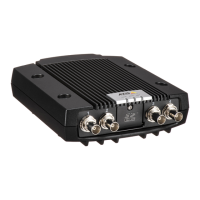
I/O Terminal connector - Used in applications for e.g. motion detection,
event triggering, time lapse recording and alarm notifications. The AXIS
Q7404 has 2 configurable inputs/outputs per video channel. These provide the
physical interface to:
• Digital output - For connecting external devices such as relays
and LEDs. Connected devices can be activated by VAPIX®, output
buttons on the Live View page or by an Event Type. The output will show as active
(shown under Events > Port Status) if the alarm device is activated.
• Digital input - An alarm input for connecting devices that can toggle between an open
and closed circuit, for example: PIRs, door/window contacts, glass break detectors, etc.
When a signal is received the state changes and the input becomes active (shown
under Events > Port Status).
Function Pin number Description
GND 1 Ground
DC Power 2 Power input 8-20V DC, max 16.1W