AXIS Q7404 Installation Guide Page 15
ENGLISH
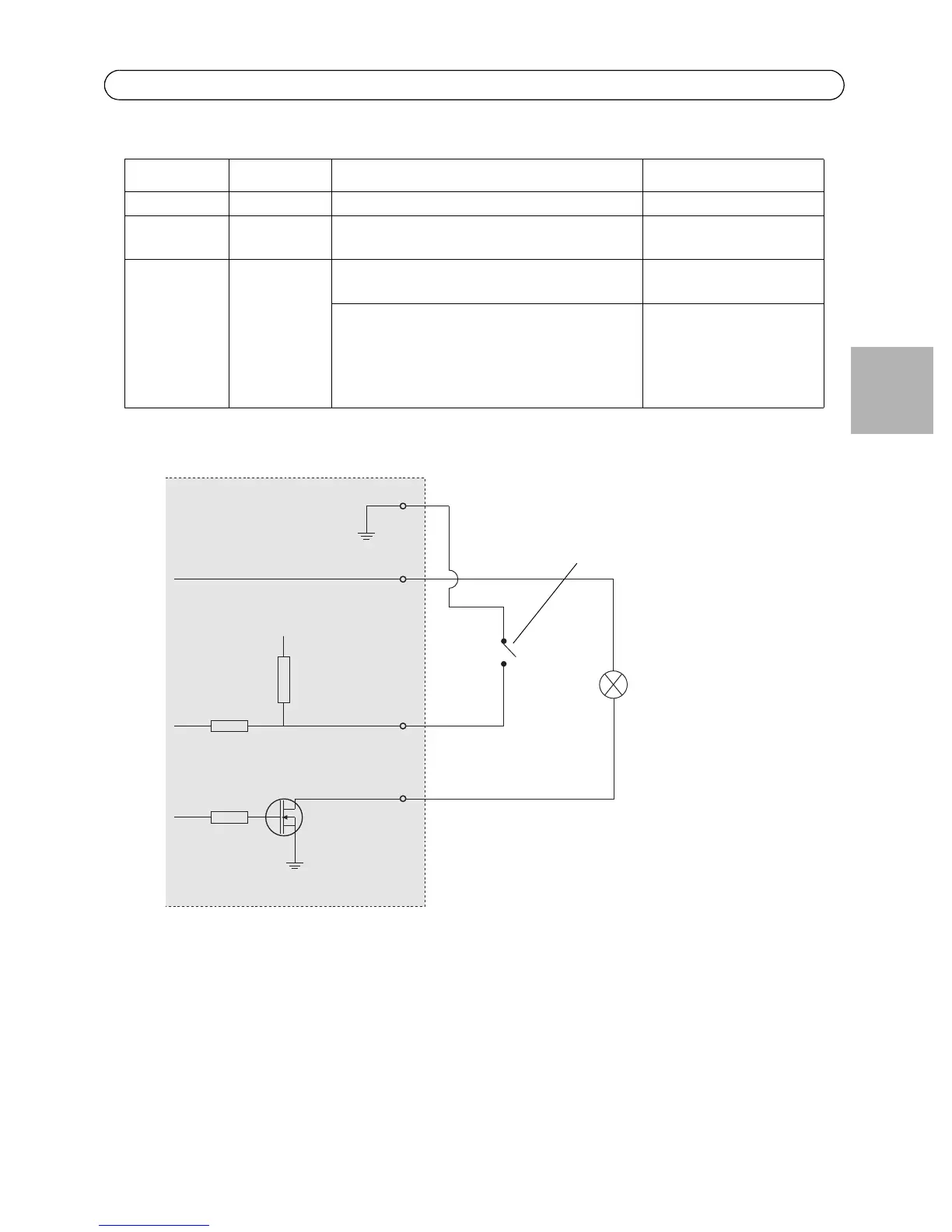
Pin assignments:
The following connection diagram gives an example of how to connect an auxiliary device to the
AXIS Q7404.
Function Pin number Notes Specifications
GND 1 Ground
3.3VDC
Power
2 Can be used to power auxiliary equipment.
Note: This pin can only be used as power out.
Max load = 250mA
Configurable
(Input or
Output)
3 - 4 Digital input - Connect to GND to activate, or
leave floating (or unconnected) to deactivate.
Min input = - 40V DC
Max input = + 40V DC
Digital output - Uses an open-drain NFET
transistor with the source connected to GND.
If used with an external relay, a diode must
be connected in parallel with the load, for
protection against voltage transients.
Max load = 100mA
Max voltage = + 40V DC
E.g. push button
I/O congured as input
I/O congured as output
AXIS Q7404
3.3V
3.3V max 250mA
D
S
G