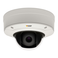
AXISV5925PTZNetworkCamera
Specifications
Digitaloutput-ForconnectingexternaldevicessuchasrelaysandLEDs.ConnecteddevicescanbeactivatedbytheVAPIX®
ApplicationProgrammingInterface,throughaneventorfromthedevice’swebinterface.
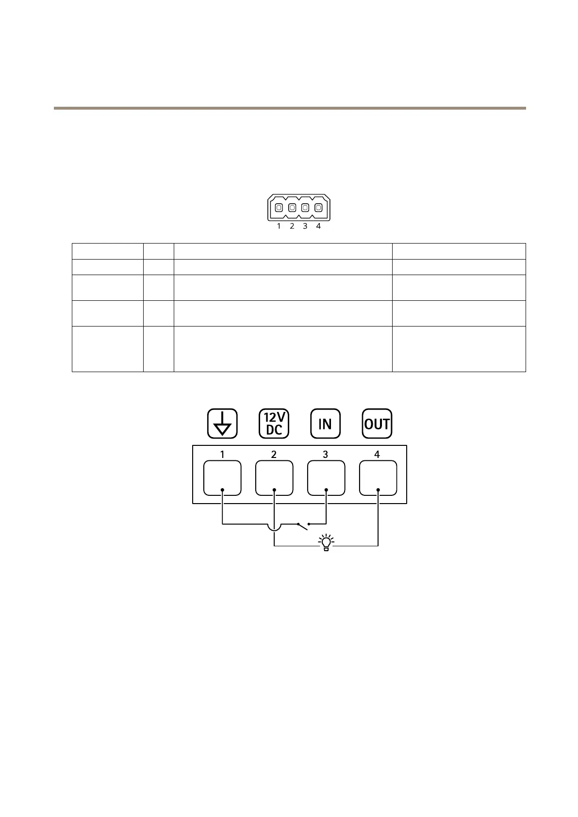
4-pinterminalblock
FunctionPinNotes
Specications
DCground
1
0VDC
DCoutput
2
Canbeusedtopowerauxiliaryequipment.
Note:Thispincanonlybeusedaspowerout.
12VDC
Maxload=25mA
DigitalInput
3
Connecttopin1toactivate,orleaveoating(unconnected)
todeactivate.
0tomax30VDC
DigitalOutput
4
Internallyconnectedtopin1(DCground)whenactive,
andoating(unconnected)wheninactive.Ifusedwithan
inductiveload,e.g.,arelay,connectadiodeinparallelwith
theload,toprotectagainstvoltagetransients.
0tomax30VDC,opendrain,
100mA
Example
1
DCground
2
DCoutput12V,max25mA
3
Digitalinput
4
Digitaloutput
Powerconnector
DCconnector.Usethesuppliedadapter.
VISCAconnector(RS-232)
6-pinterminalblockfortheRS232serialinterface.ThisisusedtocontrolthecamerausingtheVISCAprotocol.
69