4-2
4-1. Starting Communication
Before starting communication
Confirm the following points before starting communication.
Electrical wiring of the device is completed (see the “Wiring method” below).
There is an input signal from the controller (constant-current supply).
Note) If there is no 4 to 20 mA DC signal from the controller, connect a constant-current supply
(3.85 to 21.5 mA DC) to the input signal terminal. When doing so, be sure to remove the
wires coming from the controller off of the terminals.
4-1-1. Wiring method
Introduction
The wiring method for communicating with this device will now be described.
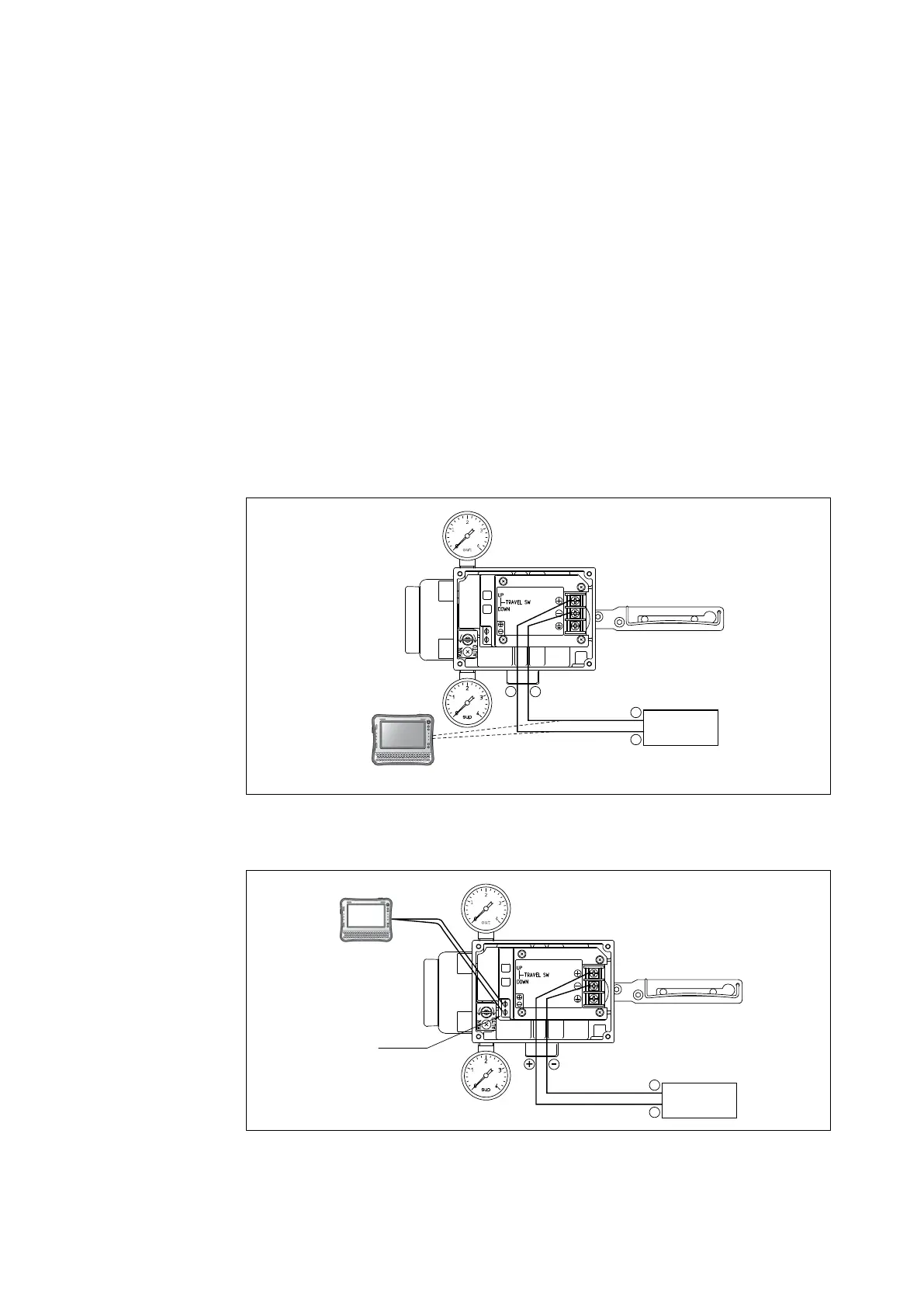
With HART® communication
Host
Controller
4-20mA DC
+
+
-
-
I IN
I IN
HART communicator
Fig. 4-1. Wiring of HART® Communication Tool (Model AVP102)
With SFN communication
Controller
4-20 mA DC
+
-
I IN I IN
Check pin
Commsta
Model (CFS100)
Fig. 4-2. Wiring with CommStaff (Model AVP100/102)

 Loading...