5-5
5-4. EPM (Electro-pneumatic converter module) balance adjustment
In situations such as when excessive mechanical shocks and other external disturbances
have been applied to the SVP itself, or when contamination from the instrumentation air has
collected in the nozzle flapper area, the internal EPM (electropneumatic converter module)
balance point may be displaced and the response characteristics degraded. This can lead to
malfunctions occurring. If the balance point displacement cannot be rectified by cleaning the
nozzle flapper area, EPM adjustment will be necessary.
CAUTION
The EPM balance adjustment can cause the valve position to change rapidly. Only perform
this adjustment in a state where no one will be injured and plant operation will not be
adversely influenced even if the valve moves suddenly.
Procedure
Step No. Procedure
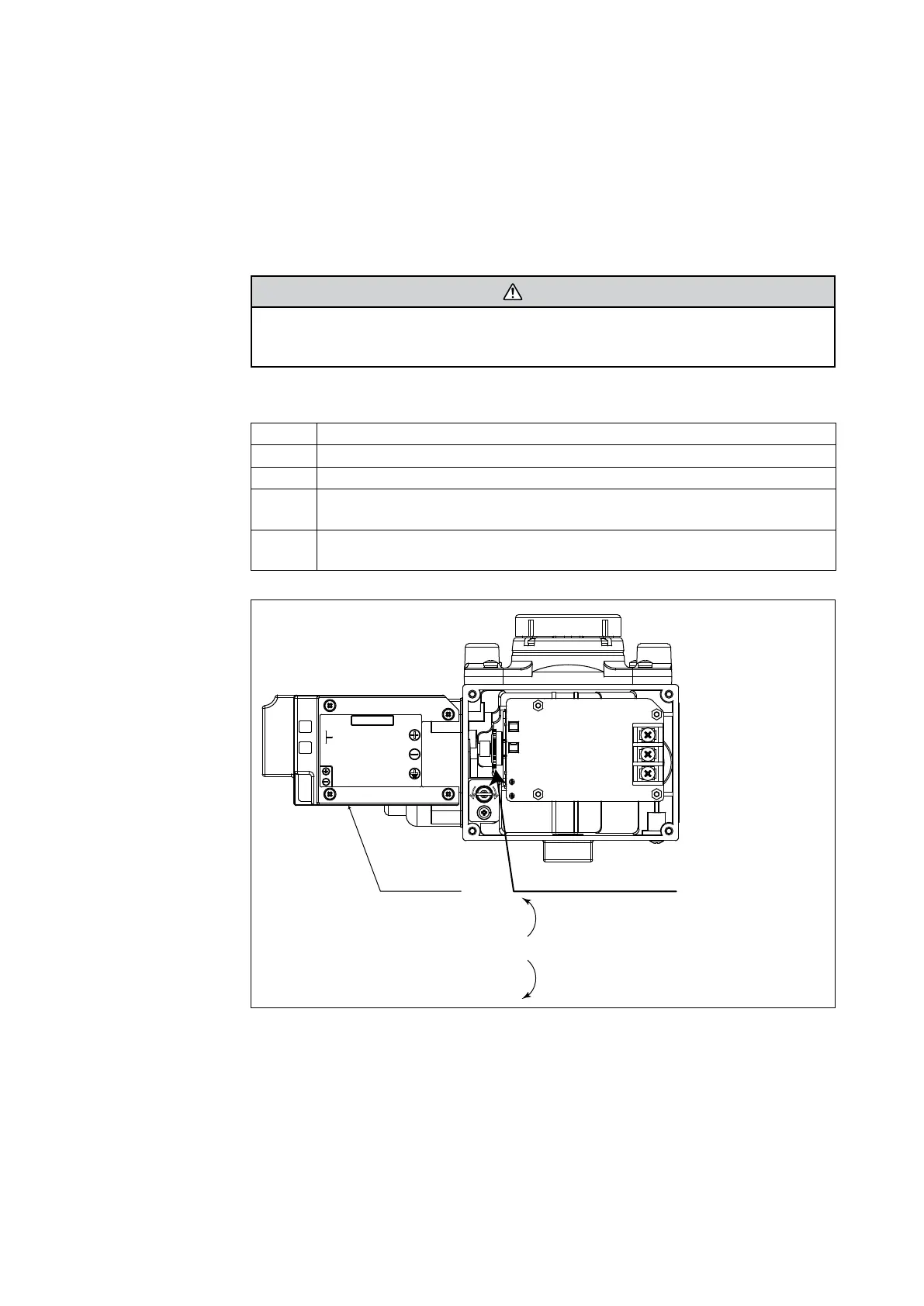
1 Remove the cover and the cover plate.
2 After supplying the stipulated air pressure, set the input signal to 50%.
3
Observe the EPM drive signal using the Commstaff. (Refer to “4-6-4. Dummy
Drive Signal” on page 4-19)
4
Adjust the EPM drive signal to have a 50% ±5% duty by turning the EPM
adjustment screw.
Cover plate
EPM adjustment screw
Turning this screw in the counterclockwise
direction increases the EPM drive signal (duty value).
Turning this screw in the clockwise direction
decreases the EPM drive signal (duty value).
AUTO
MAN.
DOWN
UP
TRAVEL SW
Fig. 5-6. EPM balance adjustment

 Loading...