4-12
Gland packing type
For the hysteresis difference due to friction of the control valve gland packing, select from
[Heavy], [Medium] and [Light]. (This is selected automatically when autosetup is executed.)
Regarding the types of gland packing, see Table 4-2 below.
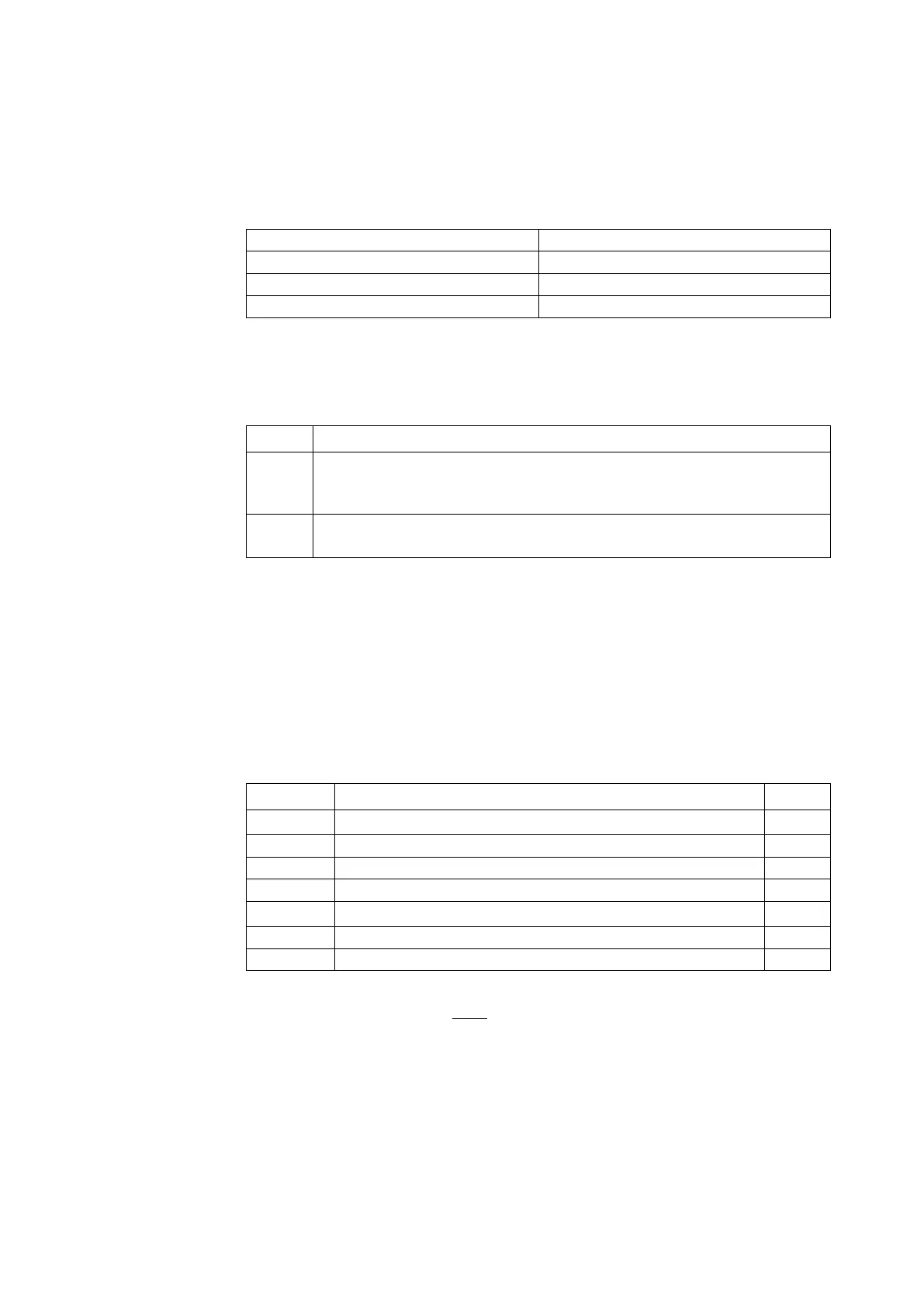
Table 4-2. Gland Packing Type Parameter Table
Hysteresis* (HYSTERESIS) Gland packing material example
Heavy (HEAVY) Graphite packing
Medium (MEDIUM) Yarn packing
Light (LIGHT) V type PTFE packing
* This cannot be decided on the basis of material because it depends on the frictional force of
the gland packing.
Gland packing type configuration procedure
step Procedure
1
Select [Device] >> [Setup] >> [Control Configuration] >> [Act. Size/Gland
Packing Type], and check the current setting. If the actuator size is 0, A, B, or C,
the gland packing type is not displayed.
2
Select [Device] >> [Setup] >> [Control Configuration] >> [Change Gland
Packing Type], and select [Light], [Medium], or [Heavy].
Gap PID parameters
For actuator size, if parameter 0 has been selected, the gap operation type PID parameters
can be set individually. The gap action PID method is utilized as the dynamic characteristics
algorithm for this device. In the gap action type PID method, deviation values (the gap) above
and below the set-point value are set up, and the PID parameters are changed depending on
whether the process value is inside or outside the gap. The merits of this method are that it is
relatively simple to tune and that it enables both fast response and stability. The meaning of
each parameter is described below.
Table 4-3. Gap Action Type PID Parameters
Parameter Parameter Meaning Units
P Reciprocal of the in-gap proportional band %
−1
I Inside-gap integrated time s
D Inside-gap differentiated time s
GE Gap width %
GP Reciprocal of the out-of-gap proportional band %
−1
GI Outside-gap integrated time s
GD Outside-gap differentiated time s
Example:
P = 2.000 indicates that 2 %
−1
=
1
0.02
% = 50 %. This means using 50 % as the proportional
band, as it is commonly called.
Note) The input setting range for these values is −19999 to +19999.
The GP, GI, and GD parameters cannot be set when GE is 0.

 Loading...