Modbus
The Modbus output parameter can be either enabled or disabled. When enabled, this output allows communications with the
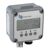
ER-500 monitor using the Modbus RTU protocol. For additional information see Modbus Interface on page 27.
At the Modbus prompt, press ENTER. The current state of the Modbus output is shown. If the current state is correct, press
ENTER to advance to the next parameter. To change the modbus setting, press UP or RIGHT to toggle between states. When
the proper state displays, press ENTER to save and advance to the BusAddr parameter.
Bus Address
If the Modbus output is enabled, you must choose a valid Modbus address. Every device communicating over the RS485
communications bus using the Modbus protocol must have a unique bus address. Address values range from 0…127 with 0
being the default.
At the BusAddr prompt, press ENTER. The first digit of the address flashes. If the current setting is correct, press ENTER to
advance to the next parameter. To change the address, press UP to increment the display digit until it matches the first digit
of the new bus address. Press RIGHT to advance to the next digit. Repeat for all digits of the address. Press ENTER to save the
new address and advance to the SetPt 1 parameter.
Setpoints
Setpoints allow the meter to signal when a specific flow condition has been achieved. They are commonly used to indicate
high or low flow conditions that need attention. The ER-500 monitor has two open collector outputs controlled by the
setpoint function.
The setpoint transistors have the same current limitations and setup requirements as the totalizing pulse output transistors
described previously. See Figure 12 on page 23 for control output transistor connections.
Both setpoint 1 and setpoint 2 are configured using the same procedures, but the hysteresis and tripping conditions can be
different for each setpoint output.
OTE:N In most instances, the current capacity of an open collector transistor is not sufficient to operate old style counters
that relied on relay contact closures. When used with basic counting circuits, a solid-state relay is needed. See Figure
13 on page 23 for a connection example.
Programming
DSY-PM-00028-EN-02Page 22 February 2017
 Loading...


