Installation
Page 16 AC_F110_BA_02_1346 November 2014
max.
50VDC
max.
50VDC
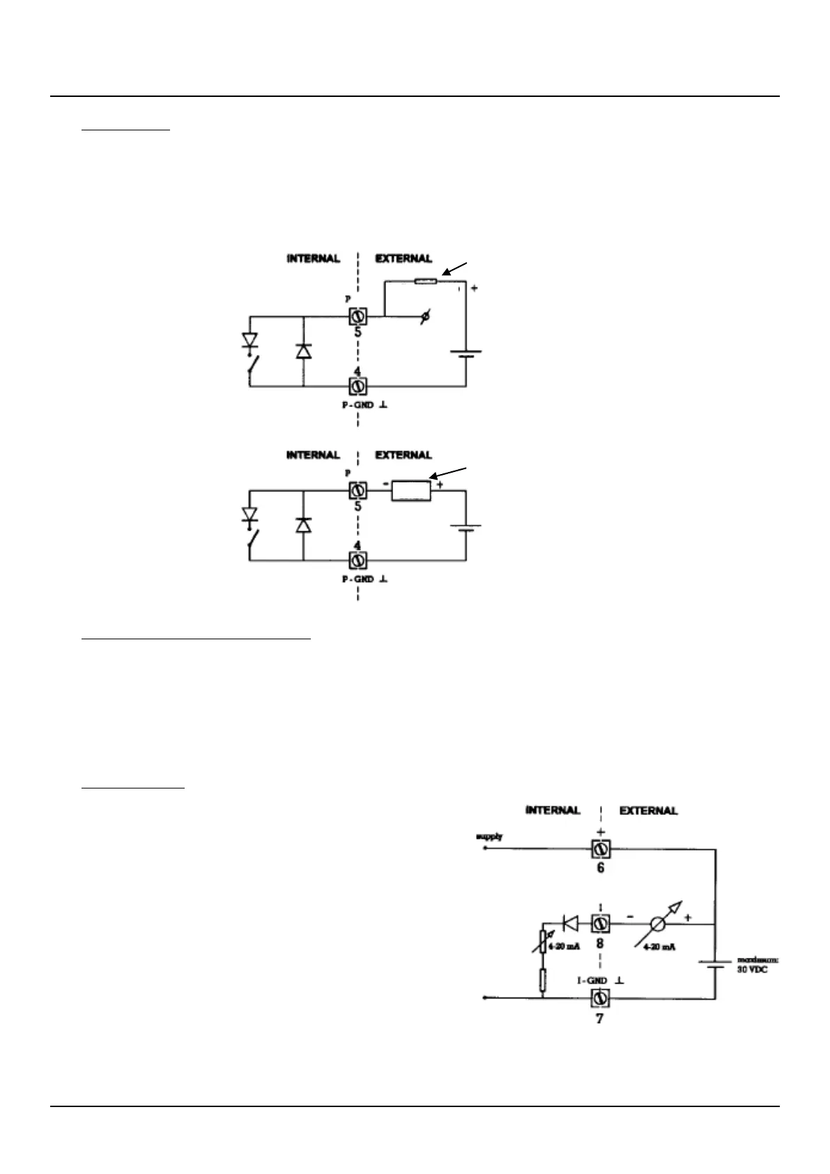
pull-up resistor
Counter device
7.5.3 PULSE OUTPUT
(connectors 4-5, SETUP 71)
An open collector output generates a pulse of 100 msec. (setting long) or 25msec. (setting short) according to a certain
quantity. This output can be used for driving an external counter relay e.g. For power-consumption reasons, it is advised to
select "OFF" when the output will not be used.
7.5.4 EXTERNAL POWER SUPPLY 5-30VAC/DC
(connectors 6-7)
5-30 volt AC/DC: connect an external power-supply to these terminals. For a DC supply connect the + to terminal 6 and the -
to terminal 7.
7.5.5 ANALOG OUTPUT
A 4-20mA-current-sink proportional to the flow rate is available. A DC
power supply should be connected to the F110 where the current is
regulated by the F110. The analogue output signal influences the
battery lifetime significantly; therefore, it is strongly advised to
connect a separate power line to connector 6. Do NOT use the same
wire as the analogue value will be incorrect! When the analogue-
output is not used, please make sure that setup 61 is disabled.

 Loading...


