Installation
November 2014 AC_F110_BA_02_1346 Page 17
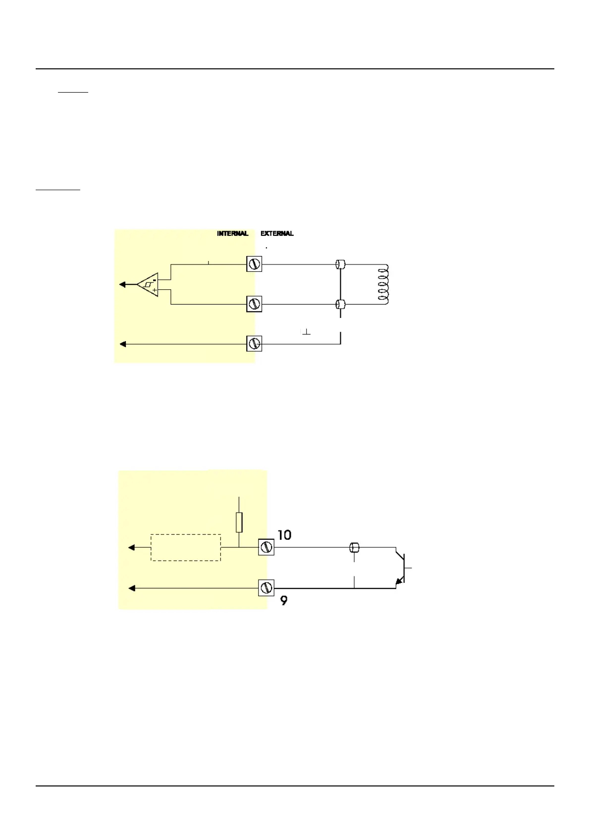
7.5.6 INPUTS
(connectors 9-12)
Two basic types of flow meter signals can be connected to the F110: pulse (terminal 10) or coil (terminal 11). The screen of the
signal wire must be connected to terminal 9 (GND). The voltage supply (3.2VDC) to the flow meter should be connected to
terminal 12. The maximum input frequency is approximately 10 kHz (depending on the type of signal).
Coil signal:
The F110 is suitable for flow meters which have a coil output. The sensitivity of the input can be selected with SETUP - 51. Two
selections can be made: COIL LO: sensitivity from about 20mV or COIL HI sensitivity from about 5mV.
Pulse signal NPN/PNP:
The F110 is suitable for flow meters which have a pulse output that is equal or almost equal to the supply voltage (3.2VDC).
For a reliable detection, the pulse amplitude has to cross 1.6VDC once per cycle. Transducers which generate a higher
amplitude than 3.2VDC can be used but the detection level is still 1.6VDC. Maximum voltage input is 10VDC for NAMUR-type
input; other inputs are rated for maximum pulse amplitudes of 24VDC.
Pulse signal NPN / NPN-LP
V ref.
1.2 VDC
Low-pass filter
selection NPN-lp

 Loading...


