Page 18/37
Operating Instructions BA 373-E66
Technical specifications subject to change
W. Bälz & Sohn GmbH & Co. Koepffstrasse 5 74076 Heilbronn Germany
Phone +49 (0)7131 15 00 0 Fax +49 (0)7131 15 00 21 www.baelz.de mail@baelz.de
Observe copyright protection DIN 34
7. POSITIONING ELECTRONICS
7.1 Operating principle of the positioning electronics
The positioning electronics is designed for the control and positioning of actuators. By applying a continuous input
signal, the positioner moves the actuator to the dened position. To do so, the positioner compares the controlled
variable (actual value) and the reference variable (set point). If these two values deviate, the positioner issues a
voltage signal (manipulated variable) to control the valve until the set point and the actual value are within a toler-
ance band. To determine the set point, a potentiometer to record the actuator's travel movement is required in the
actuator. The LEDs on the positioner board indicate the status of the positioning electronics.
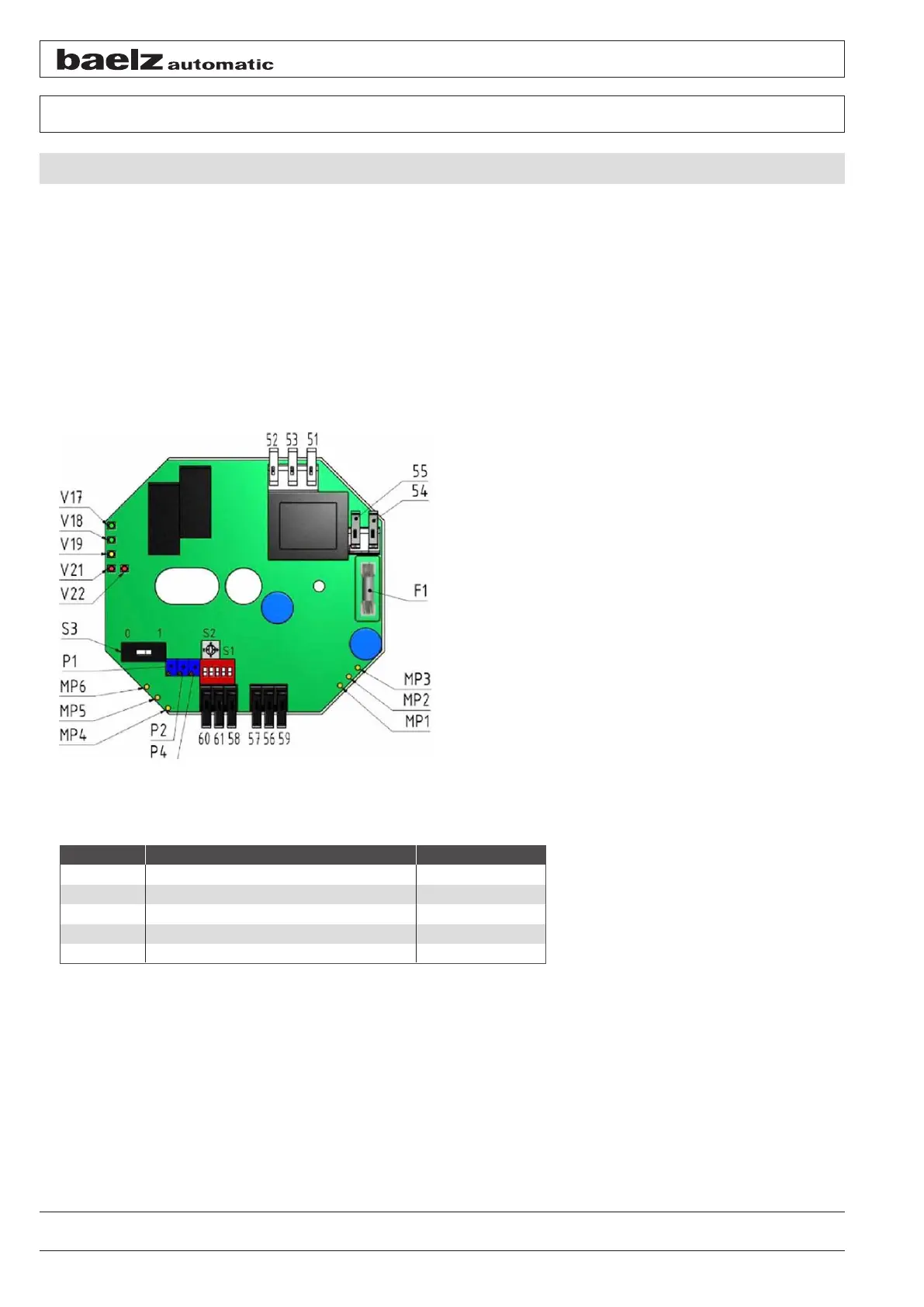
Figure 15: Positioning electronics
Use potentiometers P1, P2 and P4 as well as selector switches S2 and S3 to adjust settings, e.g. stroke calibra-
tion, split-range operation, reversed actuator action and dead band. The DIP switch settings of switch S1 allow
additional functions to be adjusted (e.g. preset zero, spreading of the potentiometer signal and behaviour upon
signal failure). The positioner comes with a minimum dead band of 200 ms to prevent sudden changes of the
actuator action or rapid activation and deactivation of the actuator. By default, the positioner has a feedback signal
that returns the current position of the valve. The signal range corresponds to the input signal range. The feedback
signal is not isolated from the input. The type of the control signal (voltage or current) is determined by the termi-
nal assignment.
LED Meaning Indicator
V17 Supply voltage ok green
V18 Actuator spindle retracts green
V19 Actuator spindle extends green
V21 Dead band active red
V22 E1 < 4 mA red