Page 19/37
Operating Instructions BA 373-E66
Technical specifications subject to change
W. Bälz & Sohn GmbH & Co. Koepffstrasse 5 74076 Heilbronn Germany
Phone +49 (0)7131 15 00 0 Fax +49 (0)7131 15 00 21 www.baelz.de mail@baelz.de
Observe copyright protection DIN 34
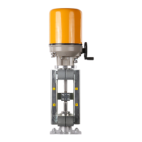
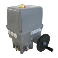
7.2 Mounting the positioning electronics
Mechanical assembly is done at the factory. After the actuator has been mounted on the valve and the switching
and signalling unit have been adjusted, set the potentiometer zero point. as described in chapter 6.4.
7.3 Electrical connection
Risk of electric shock!
Power connection and commissioning of the actuator require specialized technical knowledge regarding
the erection of electric power installations (according to DIN VDE 0100), of the accident prevention regula-
tions and of the special requirements for commissioning the linear actuator. These procedures must be
performed by qualied personnel only. Failure to heed this warning may result in death, serious injury or
substantial material damage!
● When making the electrical connection, be sure that the power supply is turned OFF! Ensure protection
against unintentional reconnection to power!
● For wiring and connection of the electrical lines, observe the DIN/VDE regulations for the erection of electric
power installations and the regulations of the local energy supplier!
● Check compliance of the line voltage and the line frequency with the specications on the identication
label of the actuator and on the identication label of the actuator motor.
● Always select the line cross section so as to match the actuator's power consumption and the required line
length. The permissible wire cross section is 0.8...2.5 mm
2
(AWG 28...12).
● Disconnection from power supply, system side: to disconnect the power supply to the actuator and de-ener-
gize the actuator for maintenance and calibration/adjustment, install a suitable main breaker in the system,
which guarantees that all poles (except the grounding conductor) are disconnected when turning off. This
main breaker must be lockable when switched off and must be protected against unintentional reconnection
to power.
● Mains protection, system side: max. 6 A.
Danger