Page 27/37
Operating Instructions BA 373-E66
Technical specifications subject to change
W. Bälz & Sohn GmbH & Co. Koepffstrasse 5 74076 Heilbronn Germany
Phone +49 (0)7131 15 00 0 Fax +49 (0)7131 15 00 21 www.baelz.de mail@baelz.de
Observe copyright protection DIN 34
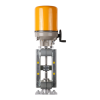
8. ELECTRONIC POSITION TRANSMITTER "ESR"
This actuator can also be equipped with an electronic position
transmitter. It is installed in the linear actuator as an additional
module in combination with a special switching and signal-
ling unit [114]. The electronic non-contact position transmitter
converts a rotary motion into an output signal. This output
signal is a DC current of 4 ... 20 mA for two-wire connection. A
special switching and signalling unit converts the axial motion
of the actuator connecting rod into a rotary motion. It features
a crown wheel which engages in the outer gear wheel of the
electronic position transmitter.
.
The electronic position transmitter is protected against re-
verse polarity.
It is designed for direct electrical connection via
two- wire connection with an output current of 4 ... 20 mA.
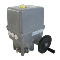
Figure 23: Top view of cover with "ESR"
8.1 Functional principle of the electronic position transmitter
The rotary motion generated by the switching and signalling unit is transmitted by the gear wheel to a rotor inside
the electronic position transmitter. The rotor position is measured with a capacitive pick-up system.
Ten stator segments (see gure 24) are excited using successive pulses (2). The phase relationship of the signal
– capacitively decoupled from the rotor – depends on the rotation angle. The signal is amplied (4) and is
converted via the phase comparator (5) and the voltage/current converter (6) into an output current proportional
to the rotation angle.
Figure 24: ESR block diagram
8.2 Electronic position transmitter specications
1 Voltage stabilization
2 Pulse generator 6 U/I converter
3 Stator-rotor 7 Three-wire connection
4 Amplier 8 Two-wire connection
5 Phase comparator 9 Load
Electrical connection Two-wire connection
Auxiliary power UH 12-30V VDC
Max. load RB 50 (UH-12) Ω
Output current 4-20 mA
Operating current max. 30mA