Page 28/37
Operating Instructions BA 373-E66
Technical specifications subject to change
W. Bälz & Sohn GmbH & Co. Koepffstrasse 5 74076 Heilbronn Germany
Phone +49 (0)7131 15 00 0 Fax +49 (0)7131 15 00 21 www.baelz.de mail@baelz.de
Observe copyright protection DIN 34
8.3 Electrical connection of the electronic position transmitter
To avoid interference, route the signal line separately from the voltage supply line to the actuator using tinned cop-
per braided sleeving.
● Remove the cable gland or dummy plug from the actuator housing
● Screw the appropriate cable gland for the shielded control cable into the actuator housing
● Remove the sheath from the cable so that the individual wires have a sufcient length for connection to
terminals 25–28
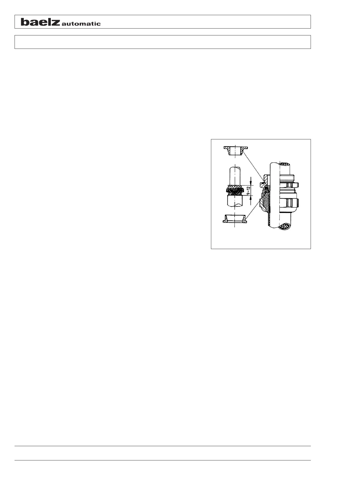
● Cut the braided sleeving to a length of approx. 9–12 mm to the outer sheath
● Then slide the union nut, the rubber seal and the inner cone bushing onto the stripped end of the cable
● Put the braided sleeving over the inner cone bushing
● Slide the outer cone bushing onto the cable end and under the
braided sleeving
● Push the cable through the lower part of the gland into the actua-
tor until the outer cone bushing stops
● Push the rubber seal into the lower part of the gland
● Screw on and tighten the union nut
● Strip the inner sheath of the cable approx. 1 cm above the actua-
tor housing
● Strip off approx. 5 mm of the insulation from the individual wire
ends
● For the stranded wires, slide the wire end ferrules onto the
stripped end and crimp them to the wires
● When routing and securing the lines in the actuator, ensure they
are protected against moving or rotating parts and will not be
damaged when removing or mounting the cover
Connection
Positive pole to terminal 25, negative pole to terminal 26; signal therefore picked up in the supply line without
return wire
Applying the operating voltage
12–30 VDC
Fig.: 25 Gland for shielded cable